Download

1 / 51
520 likes | 551 Views
POSITION SENSORS. Types of position sensors. Sensing presence Sensing Position. Sensing presence. Limit switches Photoelectric limit switch Magnetic detection Inductive proximity. Switches simplest form of digital displacement sensor

E N D
POSITION SENSORS Sensors and Measurement Instrumenattion Systems II
Types of position sensors • Sensing presence • Sensing Position Sensors and Measurement Instrumenattion Systems II
Sensing presence • Limit switches • Photoelectric limit switch • Magnetic detection • Inductive proximity Sensors and Measurement Instrumenattion Systems II
Switches • simplest form of digital displacement sensor • many forms: lever or push-rod operated microswitches; float switches; pressure switches; etc. A limit switch A float switch Sensors and Measurement Instrumenattion Systems II
Opto-switches • consist of a light source and a light sensor within a single unit • 2 common forms are the reflective and slotted types A reflective opto-switch A slotted opto-switch Sensors and Measurement Instrumenattion Systems II
Proximity Sensing: • Proximity detectors are electrical or electronic sensors that respond to the presence of a material Sensors and Measurement Instrumenattion Systems II
Inductive proximity sensors________________________ • coil inductance is greatly affected by the presence of ferromagnetic materials • here the proximity of a ferromagnetic plate is determined by measuring the inductance of a coil Inductive proximity sensors Sensors and Measurement Instrumenattion Systems II
When to Use Mechanical • Where physical contact is possible • Where definitive position is required • In operation-critical or safety-critical situations • Where environment conditions preclude the use of optical or inductive sensors Sensors and Measurement Instrumenattion Systems II
Optical Proximity Sensors • Optical Proximity Sensors Optical Proximity Sensors • Consist of a light source (LED) and light detector • (phototransistor) • Modulation of signal to minimize ambient lighting • conditions • Various models: 12-30V DC, 24-240V AC, power • Output: TTL 5V, Solid-state relay, etc. Sensors and Measurement Instrumenattion Systems II
When to use an Optical • Pros • – Non-contact, no moving parts, small. • – Fast switching, no switch bounce. • – Insensitive to vibration and shock • – Many configurations available • • Cons • – Alignment always required • – Can be blinded by ambient light conditions (welding for example) • – Requires clean, dust and water free, environment Sensors and Measurement Instrumenattion Systems II
Application • Stack height control/box counting • Fluid level control (filling and clarity) • Breakage and jam detection • And many others… Sensors and Measurement Instrumenattion Systems II
When to use Ultrasonic • Provide range data directly: • • Level monitoring of solid and liquids • • Approach warning (collisions) • • Can (usually) work in heavy dust and water • • Ambient noise is potentially an issue Sensors and Measurement Instrumenattion Systems II
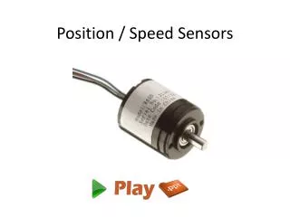
Position sensors • Resistive • Mechanically varied resistance (potentiometer) Linear and Angular potentiometer • Resistivity change (Strain gage) • Capacitive • Inductive LVDT (linear voltage differential transformer) • Reluctance Resolver and Synchro • Piezoelectric • Pulse (encoder) Linear and Rotary encoder Sensors and Measurement Instrumenattion Systems II
POTENTIOMETERS Sensors and Measurement Instrumenattion Systems II
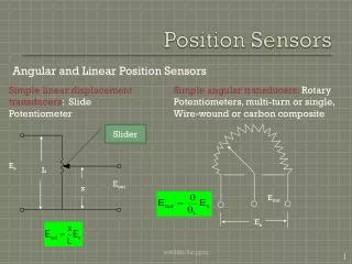
Vi l Vo x Resistive sensor : potentiometer • A potentiometer converts a linear or angular displacement into a corresponding change in ouptut voltage : • Object whose displacement is to be measured is connected to the moving contact • Output voltage is linearly related to the displacement, x • DC power • range~l •mechanical wear • Example application : positioning of robotics; e.g. in artificial limbs Sensors and Measurement Instrumenattion Systems II
Linear Position Sensors and Measurement Instrumenattion Systems II
Shaft Angle With Potentiometer • shaft angle proportional to voltage Vs • voltage Vs changes because of the change in resistance • simple application of Ohm’s law • current is constant Sensors and Measurement Instrumenattion Systems II
Angular Displacement - Potentiometer Sensors and Measurement Instrumenattion Systems II
POTENTIOMETERS Sensors and Measurement Instrumenattion Systems II
F l F Resist ivy change : strain gauge • A strain gauge is a displacement sensor whose resistance changes in response to a change in length caused by an applied force Consider a wire with length, l and cross sectional area, A : • With no force applied : • With an applied force, the length increases by Dl. • Since the total volume of the materialremains constant, the change in area is given as : and the change in resistance as : A Sensors and Measurement Instrumenattion Systems II
fixed plate movable plate Resistive sensor : strain gauge • Gauge factor, G, is given as : and may be taken as the sensitivity of the sensor • For metal wire gauges (constantan), G ~ 2, while silicon semiconductor gauges have higher sensitivity, G ~ 200 • Bonded strain gauges have folded wires bonded to a semi flexible backing material, with unbonded gauges having flexible wires connected between fixed and movable frames • a Sensors and Measurement Instrumenattion Systems II
Strain Gauge • resistance varies with the amount of stretching (strain) • flexure can be measured with a strain gauge • force can also be measured Sensors and Measurement Instrumenattion Systems II
Bridge circuits • Often the sensitivity of the basic sense element is very low; e.g. a strain gauge may produce a maximum change in resistance of only ~1% over the full operating range. It is important that this change can be accurately detected. • Sensors are often sensitive to more than one quantity; e.g. the resistance of strain gauges depends on both strain and temperature. Therefore, if the temperature of the gauge changes it produces a change in resistance which may be interpreted as a change in strain. • Two and more active sense elements can be used in a bridge circuit to increase the overall sensitivity of the sensor system. Sensors and Measurement Instrumenattion Systems II
R2 R1 + VB + R4 R3 Vo Wheatstone bridge • The basic Wheatstone bridge circuit is shown : • The output voltage is given as : by voltage divider on each leg. • The bridge is used in 2 ways – either as a null detector or as a device that reads a difference voltage directly. • For sensor circuits, the difference voltage due to deviation of one or more resistors in the bridge from an initial value is usually measured. Sensors and Measurement Instrumenattion Systems II
R R + VB + R+DR R Vo Bridge sensor circuits • Sensor bridges normally consist of 4 identical sensor elements. Consider the case when only one of these is sensitive to the quantity to be measured (other sensors are ‘dummy’ sensors) : • For example, for a max 1% change in resistance, the output voltage is ~0.0025VB; i.e. 2.5 mV for a 10 V supply. The range of Vo in this case is 0 – 2.5 mV, which can be accurately detected using a voltmeter with FSD of 2.5 mV. Consider the alternative of measuring the absolute change in resistance ! Sensors and Measurement Instrumenattion Systems II
R +DR R + VB + R+DR R Vo R R + VB + R+DR R Vo Advantages of bridge circuits • Increased measurement accuracy • Elimination of ‘noise’ effects on sensor output; i.e. if a sensor is sensitive to changes in both temperature and strain, if 4 identical elements are used with only one of them subjected to the strain, the temperature effect is cancelled • Possibility for increased sensitivity : Sensors and Measurement Instrumenattion Systems II
R +DR R + VB + R+DR R Vo Disadvantages of bridge circuits • Linearity error : E.g. For maximum DR = 1%, a linearity error of 0.5% of the FSD output voltage range is calculated. Sensors and Measurement Instrumenattion Systems II
R +DR R –DR + VB R–DR R + R+DR + R –DR VB Vo + R+DR R Vo Zero bridge linearity error • Zero-linearity error is achieved by having pairs of sensors with equal and opposite response characteristics : • Advantages of increased accuracy, increased sensitivity and immunity to noise / temperature are maintained. Sensors and Measurement Instrumenattion Systems II
Inductive and Capacitive • Inductive sensors use change in local magnetic field to detect presence of metal target • Capacitive Sensors use change in local capacitance caused by non-metallic objects • • Generally short ranges only • • Regarded as very robust and reliable Sensors and Measurement Instrumenattion Systems II
Inductive and capacitive • inductive:for detection of steel, chrome-nickel, stainless steel, brass, aluminum, copper parts • capacitive:for detection of steel, water, wood, glass, plastics Sensors and Measurement Instrumenattion Systems II
A movable plate d fixed plate Capacitive displacement sensor • A capacitive displacement sensor produces an output signal due to the change in capacitance caused by varying the distance between a fixed and a movable plate : • Example application : measuring patient respiration rate or patient movement by having several sensors placed underneath them on a bed. Sensors and Measurement Instrumenattion Systems II
+ S1 vout(t) + – P vin(t) + – S2 – ferrite rod Inductive displacement sensor (LVDT) I • A linear variable displacement transformer (LVDT) is a 3-coil inductive transducer. • Mutual inductance between the coils is changed as the position of a high permeability rod is moved between them : • Secondary windings are connected in series opposition • When the rod is centred, equal secondary voltages are induced, s.t. the output voltage is zero Sensors and Measurement Instrumenattion Systems II
Inductive displacement sensor (LVDT) Sensors and Measurement Instrumenattion Systems II
+ S1 vout(t) + – P vin(t) + – S2 – Inductive displacement sensor (LVDT) II • As the rod moves from the centre, as shown, k1 increases, while k2 decreases • vout(t) is linearly related to the change in position of the rod • AC voltage source • range is limited by extent of coils • no moving parts • Example application : repetitive displacements in robotics Sensors and Measurement Instrumenattion Systems II
Linear Variable Displacement Transformer (LVDT) • moving iron core changes properties of transformer • iron core position changes primary/secondary voltage ratio • difference in phase is measured and tranformed to a voltage Sensors and Measurement Instrumenattion Systems II
The major categories are:inductive:for detection of steel, chrome-nickel, stainless steel, brass, aluminum, copper parts • capacitive:for detection of steel, water, wood, glass, plastics Sensors and Measurement Instrumenattion Systems II
Encoder • A device used to convert linear or rotationalpositioninformation into an electrical outputsignal. Sensors and Measurement Instrumenattion Systems II
Absolute position encoders • a pattern of light and dark strips is printed on to a strip and is detected by a sensor that moves along it • the pattern takes the form of a series of lines as shown below • it is arranged so that the combination is unique at each point • sensor is an array of photodiodes Sensors and Measurement Instrumenattion Systems II
Incremental position encoder • uses a single line that alternates black/white • two slightly offset sensors produce outputs as shown below • detects motion in either direction, pulses are counted to determine absolute position (which must be initially reset) Sensors and Measurement Instrumenattion Systems II
Inductive sensor Opto-switch sensor • Other counting techniques • several methods use counting to determine position • two examples are given below Sensors and Measurement Instrumenattion Systems II
ENCODERS Sensors and Measurement Instrumenattion Systems II
INDUSTRIAL APPLICATIONS of ENCODERS Sensors and Measurement Instrumenattion Systems II