Download
1 / 80
800 likes | 977 Views
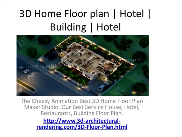
3d dynamic design of sky face hotel. Prepared by :Ahmad AL- Nuirat Islam Zuhd Supervisor: D.Abdul Razzaq Touqan. Tips to be covered . Introduction Preliminary Design And Checks Static design Dynamic checks and design . Chapter 1 : Introduction. Introduction :. Sky face hotel :

E N D
3d dynamic design of sky face hotel Prepared by :Ahmad AL-Nuirat Islam Zuhd Supervisor: D.AbdulRazzaqTouqan
Tips to be covered • Introduction • Preliminary Design And Checks • Static design • Dynamic checks and design
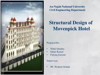
Introduction : Sky face hotel : • A four story, Nablus city. • story area = 2000 m2. • The first story is 5.5 mheight (reception, wedding hall, security, offices, restaurant, prayers room and services). • The upper three stories are 4m height for each, contain 26 living unit, and 18 sweat. • The roof contains a swimming pool ,coffee shop.
Introduction : • Site and geology: Hard lime stone, bearing capacity = 400kN/m2. • Design codes: • ACI -2008 (American Concrete Institute Code 2008 ). • IBC 2006 (international building code 2006).
Introduction : Materials : • Structural materials: Non structural materials: columns and shear walls f’c = 30 MPa. beams and slabs f’c = 24 MPa. For footing f’c = 40 MPa. Steel yield strength fy = 420 MPa. weight per unit volume fo concrete = 25 kN/m3 density =2.55 ton/m3
Introduction : • Structural system : The structural systems were used one way solid slab and two way with drop beams in both directions.
Introduction : • Loading: • Vertical loads: • Dead loads: it consists of weight of all permanent construction • super imposed dead load = 5.4kN/m2 • Live load :from table 4-1 in ASCE/SEI 7-05 code. For this building, LL = 2 kN/m2 for slab1,2,3 , LL =4.8 kN/m2 for slab roof 4 , and LL=10 kN/m2 for slab roof 5. • Lateral load from water pressure .
Introduction : • Computer programs was used: SAP2000 (v14.2.4) program. • Loads combination: Wu= 1.4D.L Wu= 1.2D.L+ 1.6L.L Wu= 1.2D.L +1.0L.L ±1.0E Wu= 0.9D.L ±1.0E
Preliminary Design And Checks • Slabs Min thickness: Table 9.5(a) in ACI-Code318-11: The most critical span is 5 m length For one end cont. span: hmin = Ln /24 For both end cont. span: hmin = Ln /28 210 mm thickness for slabs1,2,3,roof4 , and250mmfor slab roof5
Preliminary Design And Checks Check slab for shear: Own weight of slab1,2,3,roof4 =5.25 KN/m². Own weight of slabroof5 =6.25 KN/m². Wu for slab 1,2,3 = 15.98 KN/m² Wu slab roof 4 = 20.46 KN/m². Wu slab roof 5 = 29.98 KN/m². slabroof4 Vu =50.85 KN. ΦvC =97.98 KN slabroof5Vu =73.3 KN. ΦvC =122.47 KN Vu< ØVc____________ OK.
Preliminary Design And Checks • beams depths: From table 9.5(a) in ACI-Code318-11:
Preliminary Design And Checks • Columns dimensions: column( k17) : The ultimate load = 6136.59 KN Pu =Øδ (0.85*f’c*Ac + fy*As) reinforcement ratio ρ = 0.01. Ag = 400822.52 Root foot Ag = 633.11 mm Use column dimensions of 800x800.
Preliminary Design And Checks Checks and SAP model Verification: • Compatibility: The compatibility of the model was checked and it was OK
Preliminary Design And Checks Checks and SAP model Verification: • Equilibrium : Equilibrium in the vertical direction (due to gravity loads ) Thus, the errors between hand solution and SAP results are very small and less than 5%, so accept results.
Preliminary Design And Checks Checks and SAP model Verification: • Equilibrium : Equilibrium in lateral direction From hand calculation both x and Y force =0.
Preliminary Design And Checks Checks and SAP model Verification: • Stress-strain Relationship:
Slab design • Column design • Footing design • Pool design • Stair case Static design
Static design • Slab Design: • Check Deflection: The max deflection due to dead load was found at the middle of the panel between grid lines 14 and 16 that is 41.6mm.
Static design • Slab Design: • Check Deflection: Δ dead = 4.386 mm. Δ Live = 4.178 mm. Δ long term = 17.128 mm. The allowable deflection = L /240 = 5000 /240 = 20.83 mm. So the slab deflection = 17.128 mm. < allowable long term def. =20.83mmOK.
Static design • Slab Design: • check slab for shear : ØVc= 122.47 KN. ,Vu slab roof4 = 78.65 KN/m. 122.47 ≥ 78.65 OK ØVc= 97.98 KN. ,Vu slab roof4 = 56.47 KN/m. 122.47 ≥ 56.47 OK
Design for bending moment: • -ve&+ve moment m11 for slabs roof5
Static design • Design of columns: For un-braced column:- Kl/r≤ 22 ……........Short column. Kl/r≥ 22 ………….Long column
Static design M min =Pu*e min e min =0.015+0.03c Moment M min = 51.78 1 KN.m Pu =1918 KN , Mc =62.14KN.m Use =0.01 , fc =30 MPa Cover in column =0.04m ,ɤ=0.8 Pu/bh =1.74Ksi , Mn/bh2 =0.141Ksi. From interaction diagram the section is adequate to carry the load and moment .
Static design • footing: Bearing capacity of the soil=400KN/m2. • Design of footing for column B-3: Column dimensions = 0.4x0.4 m Compressive strength of concrete (fc) = 40MPa. service load =1640KN Area= Area of footing =4.1m2 The root of area =2.03m L= 2.5 m.
Static design • For design: Area of footing =6.25m2 • Check wide beam shear ØVc = 0.75fc^0.5 L*d/6 ØVc= 830.09 KN Vu = qu[ L/2– (c/2+d) ] Vu= 483.34 KN Vu < ØVc. Wide beam shear OK.
Static design • Check punching shear: Qu=306.88KN /m2 ØVcp=0.75 fc^0.5 L*d/3 ØVcp=2178.17 KN Vup=Pu –(c+d)2 qu Vup =1803 KN Vup< ØVcp Punching is OK.
Static design • Flexural design: Mu =422.92KN.m =0.00257 As= *L*d As =2699mm2 So use As 13ɸ18 As shrinkage= 2250mm2
Static design • Design of footing F7 carrying O-10 and O-13 :
Static design • Check wide beam shear was satisfied • Check punching shear was satisfied
Static design • Design of raft footing f8 : The KN and the size of mish =0.3m . stress == 325.89 KN/m2 where < 400 KN/m2 OK • Check wide beam shear: h=700mm d=620mm. ØVc = 490 KN/m • Check punching shear: ØVcp=5568.14 KN Pu on column F6= 4643 KN
Static design Design of combined footing f9: h= 60cm and d = 52cm. L = 4m. B=3 m.