Download
1 / 3
30 likes | 160 Views
Magnet Safety Systems – Magnet Common Project E. Sbrissa, G. Olesen – CERN/EP. 2.4 Fail-safe operation

E N D
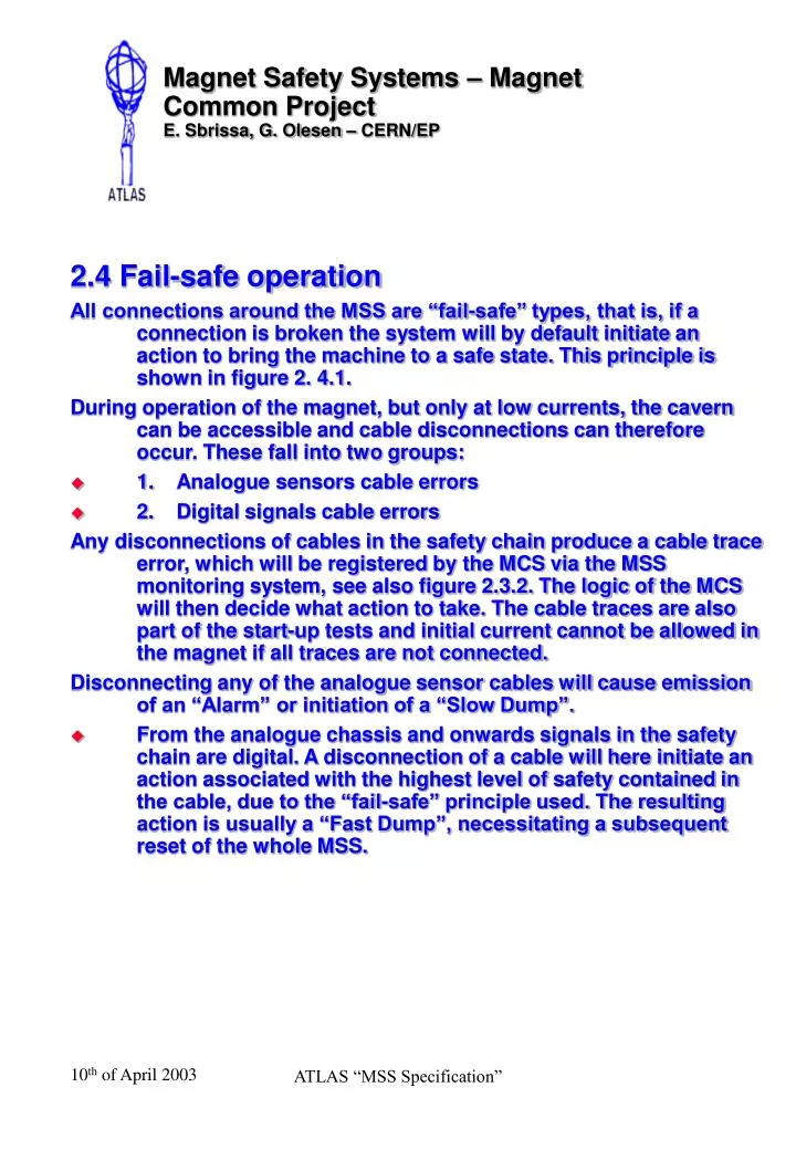
Magnet Safety Systems – Magnet Common ProjectE. Sbrissa, G. Olesen – CERN/EP 2.4 Fail-safe operation All connections around the MSS are “fail-safe” types, that is, if a connection is broken the system will by default initiate an action to bring the machine to a safe state. This principle is shown in figure 2. 4.1. During operation of the magnet, but only at low currents, the cavern can be accessible and cable disconnections can therefore occur. These fall into two groups: • 1. Analogue sensors cable errors • 2. Digital signals cable errors Any disconnections of cables in the safety chain produce a cable trace error, which will be registered by the MCS via the MSS monitoring system, see also figure 2.3.2. The logic of the MCS will then decide what action to take. The cable traces are also part of the start-up tests and initial current cannot be allowed in the magnet if all traces are not connected. Disconnecting any of the analogue sensor cables will cause emission of an “Alarm” or initiation of a “Slow Dump”. • From the analogue chassis and onwards signals in the safety chain are digital. A disconnection of a cable will here initiate an action associated with the highest level of safety contained in the cable, due to the “fail-safe” principle used. The resulting action is usually a “Fast Dump”, necessitating a subsequent reset of the whole MSS. ATLAS “MSS Specification”
Magnet Safety Systems – Magnet Common ProjectE. Sbrissa, G. Olesen – CERN/EP ATLAS “MSS Specification”
Magnet Safety Systems – Magnet Common ProjectE. Sbrissa, G. Olesen – CERN/EP 2.4 Fail-safe operation The exceptions to the fail-safe principle are the analogue levels, by definition, and the ALTERA integrated circuit used for the logic program. Window detectors on the modules, which will signal an out-of-range to the MSS monitoring system, monitor the analogue levels. This detects the cases where an analogue circuit has an internal short-circuit and the level is close to the supply voltages. Due to the internal structure of the ALTERA circuits it is not possible to certify that these are fail-safe. MSS will here rely on the quality and estimated life-time of these. The ALTERA corporation regularly up-dates their reliability reports for their circuits, and the latest, showing the data relevant to the ALTERA used in MSS, can be seen in appendix 2.4.1. It is here stated, that the corporation is ISO 9001, MIL and JEDEC certified, and uses recognized methods for reliability testing. The chip in question, EP20K200, has a combined FIT (Failure In Time) of 24 (page 13), meaning one estimated failure in 42 million device hours. ATLAS “MSS Specification”