Download
1 / 20
200 likes | 505 Views
A Compile-Time Managed Multi-Level Register File Hierarchy. Mark Gebhart Stephen W. Keckler The University of Texas NVIDIA / The University of Texas at Austin at Austin William J. Dally NVIDIA / Stanford University .

E N D
A Compile-Time Managed Multi-Level Register File Hierarchy Mark GebhartStephen W. Keckler The University of Texas NVIDIA / The University of Texas at Austin at Austin William J. Dally NVIDIA / Stanford University MICRO-44
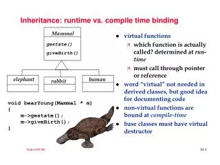
Motivation • All systems are effectively power limited • Energy efficiency is a primary design constraint • Throughput processors • Massive multithreading to tolerate memory latency • Large register file consumes significant energy • Register file hierarchy localizes most accesses to small structures close to ALUs • Compiler controls all data movement through hierarchy MICRO-44
Register Reuse Patterns • 70% of values only read once • 50% of values only read once, within 3 instructions of being written MICRO-44
Outline • Motivation • Background • Baseline GPU • Two-Level Warp Scheduler • Register File Caching • SW Managed Register File Hierarchy • Results • Conclusions MICRO-44
Baseline GPU Architecture • Similar to NVIDIA’s Fermi design • 16 streaming multiprocessors (SMs) per chip • Memory interface designed to maximize bandwidth rather than latency MICRO-44
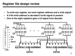
Baseline SM • Register file heavily banked for high bandwidth • 32 SIMT lanes • 1024 threads per SM • 32 warps • 32 threads per warp MICRO-44
Prior Work • Two Level Warp Scheduler • Only active warps issue instructions • Active warps descheduled on possible long latency events • Register file cache (RFC) • Hardware managed • 21 times smaller than MRF • Only active warps access RFC • RFC flushed when active warp descheduled MICRO-44
Limitations of HW Managed Cache • No knowledge of register reuse patterns • Writebacks from RFC to MRF • Must track RFC tags • Can’t privatize RFC to ALUs MICRO-44
Outline • Motivation • Background • SW Managed Register File Hierarchy • Microarchitecture • Compiler Algorithms • Results • Conclusions MICRO-44
Microarchitecture • Main Register File (MRF) • 128KB for 1024 threads • Operand Register File (ORF) • 3 entries * 256 active threads • Last Result File (LRF) • 1 entry * 256 active threads • Private to ALUs MICRO-44
Allocation for Hierarchical Register File • Split program into allocation units called strands • Strand is sequence of instructions with no long latency dependencies • All inter-strand values communicated through MRF • To simplify allocation: • A backwards branch ends a strand • A basic block targeted by a backwards branch begins a strand • Compiler marks end of strands BB1 ld.global R1 read R1 Strand 1 * * * Strand 2 End of strand marker Strand 3 BB2 add add Strand 4 BB3 MICRO-44
Allocation Algorithm LRF ORF MRF R3 R4 R6 R6 R5 R7 • Greedy per strand • Metric: energy savings/lifetime add R3, R1, R2 sub R4, R1, R3 mul R6, R3, R3 ld.global R5, R4 add R7, R6, R6 div R8, R5, R6 add R9, R7, R8 MICRO-44
Optimizations • Partial range allocation • Read operand allocation • Split LRF MICRO-44
Optimization #1 • Partial range allocation R1 written to both ORF and MRF Reads of R1 come from ORF Strand Read of R1 comes from MRF MICRO-44
Optimization #2 • Read operand allocation R0 is read from MRF and written to ORF Strand Reads of R0 come from ORF MICRO-44
Outline • Motivation • Background • SW Managed Register File Hierarchy • Results • Register Access Breakdown • Energy Savings • Conclusions MICRO-44
Breakdown of Register Accesses • LRF is able to handle 30% of traffic MICRO-44
Energy Evaluation • Max energy savings of 54% with 3 level SW control and 3 ORF entries per thread • 44% improvement over prior hardware controlled RFC 2 Level HW 3 Level HW 2 Level SW 3 Level SW Number of ORF/RFC Entries per Thread MICRO-44
Individual Benchmark Results • 3 level SW design with 3 ORF entries per active thread MICRO-44
Conclusion • 3-level SW controlled design reduces register file energy by 54% • 8.3% savings in SM dynamic energy • 5.8% savings in chip-wide dynamic energy • Limit study highlights potential for future work to improve results • Instruction scheduling concurrently with allocation • Throughput processors have different critical structures • Must redesign as we enter power limited world MICRO-44