Download

1 / 36
1.06k likes | 2.54k Views
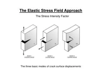
The Elastic Stress Field Approach The Stress Intensity Factor. The three basic modes of crack surface displacements. Derivation of the Elastic Stress Field Equations. Concepts of plane stress and plane strain Equilibrium equations Compatibility equations for strains Airy stress function

E N D
The Elastic Stress Field Approach The Stress Intensity Factor The three basic modes of crack surface displacements
Derivation of the Elastic Stress Field Equations • Concepts of plane stress and plane strain • Equilibrium equations • Compatibility equations for strains • Airy stress function • Biharmonic equation • Complex stress functions: Westergaard function for biaxially loaded plate (Mode I) • Mode I stress / displacement fields • Mode I stress intensity factor Westergard (1939), Irwin (1957)
Mode I: Linear Elastic Crack-tip Fields (general case)
Mode III: Mode II:
- The stress and displacement formulas may reduced to particularly simple forms: Angular distributions of crack-tip stresses for the three modes (rectangular: left; polar:right) CHARACTERISTICS OF THE STRESS FIELDS • Details of the applied loading enters only through K!!! • for the infinite plate: K = s(p*a)1/2 • But for a given Mode there is a characteristic shape of the field !!! - Principle of Superposition: for a given Mode, K terms from superposed loadings are additive
edge notched finite width We consider next some other cases apart from the cracked infinite plate • Semi infinite edge notched specimens • Finite width centre cracked specimens • Finite width edge notched specimens • Crack-line loading • Elliptical / Semielliptical cracks
f(a/W) Irwin: Brown: approx. Isida:36 term power series Feddersen: Finite-width centre-craked specimens:
Semi infinite edge-notched specimens: Free edges: crack opens more than in the infinite plate resulting in 12% increase in stress Single edge notched (SEN) Double edge notched (DEN) SEN: Finite-width edge-notched specimens: 0.5% accurate for a/W < 0.6 DEN: 0.5% accurate for any a/W
Crack under internal pressure (force per unit thickness is now P.dx, where P is the internal pressure) same result by end loading with s ! TWO IMPORTANT SOLUTIONS FOR PRACTICAL USE * Crack-line Loading (P: force per unit thickness) for centrally located force: KI decrease when crack length increases ! • Very useful solution: • Riveted, bolted plates • Internal Pressure problems
Example: corner crack in a longitudinal section of a pipe-vessel intersection in a pressure vessel actual cracks often initiate at surface discontinuities or corners in structural components !!! * Elliptical Cracks We start considering idealised situations: from embeded elliptical crack to semielliptical surface cracks
Where F: elliptic integral of the second type Irwin solution for Mode I: with: During crack growth an elliptical crack will tend to become circular: important in fatigue problems max. at =p/2: KI varies along the elliptical crack front circular crack: min. at =0: The embeded (infinite plate) elliptical crack under Mode I loading
Raju I.S.,Newman J.C. Jr. Stress Intensity Factors for Two Symmetric Corner Cracks, Fracture Mechanics, ASTM STP 677, pp. 411-430 (1979). The semi- elliptical surface crack in a plate of finite dimensions under Mode I loading In practice elliptical cracks will generally occur as semi-elliptical surface cracks or quarter-elliptical corner cracks Best solutions for semielliptical: FEM calculations from Raju-Newman:
2) Semi-elliptical Surface Crack in a Cylindrical Pressure Vessel: SUPERPOSITION OF STRESS INTENSITY FACTORS 1) Crack under Internal Pressure:
3) Cracks growing from both sidesof a loaded hole where the hole is small with respect to the crack where P is the force per unit thickness
First approximation: Better approaches • selected shape: better size estimation • Irwin • Dudgale • Better shape but first order approximation for the size Irwin approach: - stress redistribution; elastic – plastic; plane stress CRACK TIP PLASTICITY
Through-thickness plastic zone in a plate of intermediate thickness Plastic zone shape from Von Mises yield criterion First Order Aproximations of Plastic Zone Shapes • Empirical Rules to estimating Plane Stress vs. Plane Strain conditions: • Plane Stress: 2.ry ≈ B • Plane Strain: 2.ry < 1/10 B
Planes of maximum shear stress: location of the planes of maximum shear stress at the tip of the crack for plane stress (a) and plane strain (b) conditions
Under conditions of: - small scale plasticity - plane strain Kc = KIC Variation in KC with specimen thickness in a high strength maraging steel FRACTURE TOUGHNESS Is K a useful parameter to characterise fracture toughness? KIC is a material property: fracture toughness of linear elastic materials
Effect of Specimen Thickness on Mode I Fracture Toughness • Limits to the Validity of LEFM: • After considerable experimental work the following minimum specimen size requirements were established to be in a condition of : • plane strain • small scale plasticity Remember:Empirical Rules to estimate Plane Strain conditions:2*ry < 1/10 B
where ASTM Standard Single Edge notched Bend (SENB) Specimen where ASTM Standard Compact Tension (CT) Specimen LEFM Testing: ASTM E-399, committee E8 Fatigue and Fracture Fatigue pre-cracked specimens !
Principal types of load-displacement plots obtained during KIC testing Clip gauge and ist attachment to the specimen • ANALYSIS • Line at 5% offset (95 % of tg OA equivalent to 2 % crack extension • Ps: intersection 5 % offset with P-v record • if there is a P value > Ps before Ps, then PQ = Ps • check if Pmax / PQ < 1.10, then • go to K(PQ): calculate KQ (conditional KIC) • check if for KQ the specimen size requirements are satisfied, then • check if crack front is symmetric, then • KQ = KIC (valid test)
Material Toughness Anisotropy To provide a common scheme for describing material anisotropy, ASTM standardized the following six orientations: L-S, L-T, S-L, S-T, T-L, and T-S. The first letter denotes the direction of the applied load; the second letter denotes the direction of crack growth. In designing for fracture toughness, consideration of anisotropy is very important, as different orientations can result in widely differing fracture-toughness values. When the crack plane is parallel to the rolling direction, segregated impurities and intermetallics that lie in these planes represent easy fracture paths, and the toughness is low. When the crack plane is perpendicular to these weak planes, decohesion and crack tip blunting or stress reduction occur, effectively toughening the material. On the other hand, when the crack plane is parallel to the plane of these defects, toughness is reduced because the crack can propagate very easily.
* SUBCRITICAL CRACK PROPAGATION IN COMPONENTS WITH PREXISTING FLAWS Fatigue • Sustained load crack growth behaviour • - stress corrosion cracking • cracking due to embrittlement by internal or external gaseous hydrogen • liquid metal embrittlement • creep and creep crack growth
DKmax = KIC (1-R) !! Fatigue crack growth rate curve da/dN - DK Fatigue Crack Propagation
Paris Law: only Region II, no R effects also Region III Forman: complete crack growth rate curve n1, n2, n3, empirically adjusted parameters Complete curve the three regions McEvily: How to describe crack growth rate curves: crack growth “laws“
Fatigue crack growth rate for Structural steel (BS4360) at room temperature and with cycling frequencies 1-10 Hz. Fatigue crack growth rate vs. DK for various structural materials at low R values EXAMPLES of Crack Growth rate Behaviour
Effect of R: Influence of R on fatigue crack growth in Al 2024-T3 Alclad sheet CRACK CLOSURE
Measuring the crack opening stress by means of a stress-displacement curve Elber: Actually: Crack closure effects
Initial KI !!! Sustained load crack growth behaviour Time to Failure Tests: preferred technique in the past
KISCC KIC or KQ Generalised sustained load crack growth behaviour Modern techniques: based on fracture mechanics parameter K !
SPECIMENS Increasing or decreasing K specimens crack- line wedge-loaded specimen (CLWL) tapered double cantilever beam-specimen (TDCB): constant K !!! bolt loaded cantilever beam-specimen (DCB)
Decreasing K specimens: Advantages: Difference in crack growth behaviour for increasing K (cantilever beam) and decreasing K (modified CLWL or DCB specimens) Entire crack growth with one specimen Self stressed and portable Claer steady state and arrest Corrosion product wedging: gives higher crack growth rate at a given nominal KI. Disadvantages:
Example: Outdoor exposure stress corrosion cracking propagation in 7000 series Al-alloy plate