Download
1 / 21
300 likes | 739 Views
Wireless Power Transfer. Team : SARAH MUSBAH AMAL ALOSH. Objective. Client needs to charge a device that is not directly connected to a source, i.e. No Wires!. Sub-Project for Saleh Alamassy.

E N D
Wireless Power Transfer Team: SARAH MUSBAH AMAL ALOSH
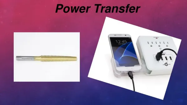
Objective Client needs to charge a device that is not directly connected to a source, i.e. No Wires! Sub-Project for SalehAlamassy Construct a testing device for a wireless charging system. Device will be used system set-up and deployment.
Requirements • Transmit power wirelessly at least 24 inches • Produce 5-V / 10W output to receivers • Transmission frequency should be greater than 2MHz • System must utilize Magnetic Induction • Primary side must plug into a wall outlet • Must charge a device • (Sub-project) Must have testing device http://www.leggettecoupled.com/how-ecoupled-technology-works.asp
Project Impact • Societal Effects of Wireless Power • Convenience • Reduces clutter in workspaces, homes, etc. • Variety of Applications • Health and Safety Concerns • Believed to pose no health risks • Environmental Impact • Battery disposal • Ethical Issues • FCC compliance with other devices http://www.gizmodo.com.au/2009/08/duracells-smart-power-lineup-includes-wireless-gadget-charging-pad/
Magnetic Resonant Induction Resonance Tuning • AC power is supplied at the system operating frequency • The inductor and capacitor are chosen so that they resonate at the operating frequency, creating a much larger magnetic field • By placing a resonant receiver within the magnetic field, a resonant circuit is created • This resonant circuit allows the system to pass voltage and current to the receiver over significant separation distance http://media.popularmechanics.com/images/witricity-0907a.jpg
Full System Schematic Test Receiver Tuning Capacitor Tuning Capacitor Viking I RF Amplifier Primary Coil Source Side Charging Receiver Receiving Coil Tuning Capacitor USB Out Voltage Regulator LED Array Receiving Coil
Source Side – Problems Colpitts Oscillator Power Amplifier • Creates output AC signal at designed • frequency • Extremely robust • Colpitts Oscillator provides small signal input • Can provide at least 30W output for up to 7MHz frequency • Simulation • Mounting • Heat Dissipation • Signal Quality • Frequency Compatibility • Mounting • Heat Dissipation • Compatibility With Coils http://www.cirrus.com/en/pubs/proDatasheet/PA107U_A.pdf http://www.biocrawler.com/w/images/f/f6/NPN_Colpitts_oscillator_collector_coil.png
Source Side – Solution • Provides oscillation frequency and • power amplification • Driven by crystal oscillators (8.5 MHz) • Tunable output power • Connect to coils through coax cable • Cost and Project Requirements Viking 1 ($120, 80lbs) Tokyo HL-100DBX ($805, 5lbs)
Wireless Channel – Design Design Features • Helical Coils • Coil geometry selected to maximize inductance • Capacitance can be tuned to resonance • Resonance can be achieved with a variety of geometries http://www.advancedtubular.com/wiki/images/thumb/a/a8/Coilpitch.jpg/400px-Coilpitch.jpg
Charging Receiver – Design Design Features • Full-Wave Rectifier must handle MHz frequency and up to 15W • Voltage Regulator will provide 10W 5V dc output for charging device • Charger, plan to charge a phone with a phone charger. http://www.robotshop.us/dimension-engineering-de-swadj-1.html?utm_source=google&utm_medium=base&utm_campaign=jos http://upload.wikimedia.org/wikipedia/commons/c/cc/Gratz.rectifier.en.png
Testing Device – Plan Same coil design as Charging Receiver. Wattmeter to display amount of power received. LED array for visual indication of signal strength . http://www.newegg.com/product/product.aspx?Item=N82E16882715001
Testing Device – Design Test Receiver • 3 stage LED array to identify field strength • Each LED has a different resistor in series • As field strength increases, enough power is increased to illuminate each successive LED Tuning Capacitor Led 1 on Led 1 & 2 on LED Array Led 1 & 2 & 3 on Receiving Coil http://www.netgate.com/support/Drivers/STA_24071bin/ACU/Manual/images/tray_icons.gif
Source Side – Testing Status: • Clean waveform at 8.5MHz • Multiple power outputs available • Current could not be measured due to frequency limit of multimeters 30W 60W 18W
Wireless Channel – Design • BC-610 PA’s did not have a high enough inductance to transfer power • All constructed coils were able to resonate • Without grounding, power was received at 3ft • With grounding, power was received at 8ft Un-grounded Test AWG 18 37 turns 39.3 µH BC-610 PA 5.1 µH AWG 12 65 turns 49.1 µH
Charging Receiver – Test Results Charging Test Oscilloscope Waveform • Successfully rectified and regulated signals. • Typically used pre-built adapters for charging devices. • Most higher end devices have required turn on voltages which are difficult to achieve. • Virtually no error or difficulties in testing the receiving side with the system.
Testing Issues Plate Current Limit • Cannot use crystals above 8.5MHz Frequency of Operation • High failure rate for LEDs • Resonance with Oscilloscope • Multi-meter frequency limit Grounding http://painawaynow.com/WP/images/tesla.jpg • Difficulties creating virtual ground • Arcing has occurred due to grounding issues • Best results have been achieved when receiving coil is properly grounded (i.e. connected to ground with a wire!)
Questions? http://neatorama.cachefly.net/images/2009-04/tesla-rodin-thinker.jpg