Download
1 / 28
280 likes | 294 Views
EE462L, Spring 2013 H-Bridge Inverter Basics. !. H-Bridge Inverter Basics – Creating AC from DC. Single-phase H-bridge (voltage source) inverter topology:. Switching rules. •. Either A+ or A. –. is closed,. but never at th. e same time *. Vdc. •. Either B+ or B. –. is closed,.

E N D
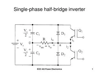
! H-Bridge Inverter Basics – Creating AC from DC Single-phase H-bridge (voltage source) inverter topology: Switching rules • Either A+ or A – is closed, but never at th e same time * Vdc • Either B+ or B – is closed, but never at the same time * *same time closing would cause a short circuit from Vdc to ground (shoot-through) *To avoid dhoot-through when using real switches (i.e. there are turn-on and turn-off delays) a dead-time or blanking time is implemented A+ B+ Va Vb Load A – B – Corresponding values of Va and Vb • A+ closed, Va = Vdc • A – closed, Va = 0 • B+ closed, Vb = Vdc • B – closed, Vb = 0
Corresponding values of Vab • A+ closed and B – closed, Vab = Vdc • A+ closed and B+ closed, Vab = 0 • B+ closed and A – closed, Vab = – Vdc • B – closed and A – closed, Vab = 0 H BRIDGE INVERTER Vdc A+ B+ • The free wheeling diodes permit current + Vdc − to flow even if al l switches are open Va Vb Load • These diodes also permit lagging currents to flow in inductive loads A – B –
Corresponding values of Vab • A+ closed and B – closed, Vab = Vdc • A+ closed and B+ closed, Vab = 0 • B+ closed and A – closed, Vab = – Vdc • B – closed and A – closed, Vab = 0 H BRIDGE INVERTER Vdc A+ B+ • The free wheeling diodes permit current + 0 − to flow even if al l switches are open Va Vb Load • These diodes also permit lagging currents to flow in inductive loads A – B –
Corresponding values of Vab • A+ closed and B – closed, Vab = Vdc • A+ closed and B+ closed, Vab = 0 • B+ closed and A – closed, Vab = – Vdc • B – closed and A – closed, Vab = 0 H BRIDGE INVERTER Vdc A+ B+ • The free wheeling diodes permit current − Vdc + to flow even if al l switches are open Va Vb Load • These diodes also permit lagging currents to flow in inductive loads A – B –
Corresponding values of Vab • A+ closed and B – closed, Vab = Vdc • A+ closed and B+ closed, Vab = 0 • B+ closed and A – closed, Vab = – Vdc • B – closed and A – closed, Vab = 0 H BRIDGE INVERTER Vdc A+ B+ • The free wheeling diodes permit current + 0 − to flow even if al l switches are open Va Vb Load • These diodes also permit lagging currents to flow in inductive loads A – B –
H-Bridge Inverter • Square wave modulation:
Corresponding values of Vab • A+ closed and B – closed, Vab = Vdc • A+ closed and B+ closed, Vab = 0 • B+ closed and A – closed, Vab = – Vdc • B – closed and A – closed, Vab = 0 ! Basic Square Wave Operation(sometimes used for 50 Hz or 60Hz applications) Vload Vdc −Vdc The Vab = 0 time is not required but can be used to reduce the rms value of Vload
! Many Loads Have Lagging Current – Consider an Inductor There must be a provision for voltage and current to have opposite signs with respect to each other Vload Vdc −Vdc Iload I −I
Load Current Can Always Flow, Regardless of Switching State Example - when current flows left to right through the load Vdc A+ B+ here or here Va Vb Load A – B – here or here
Load Current Can Always Flow, cont. Example - when current flows right to left through the load Vdc A+ B+ here here Va Vb Load A – B – or here or here
Load Current Can Always Flow, cont. H BRIDGE INVERTER Corresponding values of Vab • A+ closed and B – closed, Vab = Vdc Vdc • A+ closed and B+ closed, Vab = 0 • B+ closed and A – closed, Vab = – Vdc • B – closed and A – closed, Vab = 0 •Load consuming power A+ B+ •Load generating power + Vdc − Va Vb Load A – B –
Load Current Can Always Flow, cont. H BRIDGE INVERTER Corresponding values of Vab • A+ closed and B – closed, Vab = Vdc Vdc • A+ closed and B+ closed, Vab = 0 • B+ closed and A – closed, Vab = – Vdc • B – closed and A – closed, Vab = 0 •Load consuming power A+ B+ •Load generating power + Vdc − Va Vb Load A – B –
! The four firing circuits do not have the same ground reference. Thus, the firing circuits require isolation. Vdc (source of power delivered to load) + + A B Local ground Local ground + + reference for A reference for B firing circuit firing circuit S S Load – – A B Local ground Local ground − − reference for A reference for B firing circuit firing circuit S S
H-Bridge Inverter • Harmonics with square wave modulation
! Vload Vdc −Vdc Question - How can a sinusoidal (or other) input signal be amplified with low distortion? Answer – the switching can be controlled in a smart way so that the FFT of Vload has a strong fundamental component, plus high-frequency switching harmonics that can be easily filtered out and “thrown into the trash” Progressivelywider pulses at the center Progressively narrower pulses at the edges Unipolar Pulse-Width Modulation (PWM)
! Vcont > Vtri , close switch A+, open switch A – , so voltage Va = Vdc Vcont < Vtri , open switch A+, close switch A – , so voltage Va = 0 – Vcont > Vtri , close switch B+, open switch B – , so voltage Vb = Vdc – Vcont < Vtri , open switch B+, close switch B – , so voltage Vb = 0 Implementation of Unipolar Pulse Width Modulation (PWM) Vcont is the input signal we want to amplify at the output of the inverter. Vcont is usually a sinewave, but it can also be a music signal. Vcont Vtri −Vcont The implementation rules are: Vtri is a triangle wave whose frequency is at least 30 times greater than Vcont. Ratio ma = peak of control signal divided by peak of triangle wave Ratio mf = frequency of triangle wave divided by frequency of control signal
Ratio ma = peak of control signal divided by peak of triangle wave Ratio mf = frequency of triangle wave divided by frequency of control signal Load voltage with ma = 0.5 (i.e., in the linear region)
Load voltage with ma = 1.5 (i.e., overmodulation)
V 4 dc · p 2 V dc ! 2 Variation of RMS value of no-load fundamental inverter output voltage (V1rms ) with ma For single-phase inverters ma also equals the ratio between the peak output voltage and the input Vdc voltage. V 1rms asymptotic to square wave value ma is called the modulation index m a 0 1 linear overmodulation saturation
RMS magnitudes of load voltage frequency components with respect to for ftri >> fcont
! PWM controlled H-Bridge Inverter • Very efficient • Distortion higher than linear amplifier, but a linear amplifier has, at best, 50% efficiency • Perfectly suited for motor drives where voltage and frequency control are needed • Well suited for bass music amplification, such as automotive applications, or where high power is more important than a little loss in quality