Download
1 / 25
250 likes | 264 Views
Imaging Nuclear Reactions. Zhon Butcher 2006 REU Program Cyclotron Institute Mentor: Dr. Robert Tribble. Applications of Nuclear Imaging. Space Telescopes – Cosmic radiation identification and direction of origin. Imaging reactions in the nuclear physics laboratory.

E N D
Imaging Nuclear Reactions Zhon Butcher 2006 REU Program Cyclotron Institute Mentor: Dr. Robert Tribble
Applications of Nuclear Imaging • Space Telescopes – Cosmic radiation identification and direction of origin. • Imaging reactions in the nuclear physics laboratory.
How Imaging Works in the Lab • Several detectors are placed around the reaction site covering a given solid angle. • Detectors determine particle identity and position. • The resulting image gives a picture of the reactions that took place in the chamber.
Particle Identification • Telescopes: Front detector and rear detector. • Front detector picks up energy loss as the particle passes through. • Rear detector picks up residual energy. • Particle identification determined by:
Methods for Position Determination • Many small detectors coupled with a large amount of electronics (clustering). • Resistive strip detectors. • Double sided strip detectors. • Resistive sheets.
Q1 Q2 Qtot 1-D Position Sensitive Detector
Resistive Strip Detectors • Consist of many resistive strips placed alongside one another. • Good resolution in the X direction, poor resolution in the Y direction (or vice versa depending on orientation).
Double Sided Strip Detectors • Two sheets of strips placed one in front of the other so the strips form a grid. • Results in better position resolution • Washington University team had detectors with 32 strips in each direction. • 64 strips per detector x 4 detectors = 256 channels for position reconstruction
Resistive Sheets • A single resistive sheet spans the entire active area of the detector. • Advantages • Fewer signals to process. • Less electronic equipment. • Detector Types: • Duo-lateral: Generates two signals from each face of the detector, two from the front and two from the back. • Tetra-lateral: Generates five signals, one from each corner of the resistive side, and one signal from the back.
Bias 1 MW 10 kW 10 kW 10 kW 10 kW 10 kW 10 kW Schematic diagram of the detector 10 kW 10 kW Tetra Lateral Detectors Particle impinging position calculated by:
Signal Processing ADC Preamplifier Spectroscopy Amplifier Preamplifier Spectroscopy Amplifier Detector Computer Preamplifier Spectroscopy Amplifier Preamplifier Spectroscopy Amplifier Gate Generator Preamplifier Timing Amplifier Discriminator Rear signal
Doped Semiconductor What is doping? • Doping is the integration of impurities into the lattice structure of the semiconductor. • This allows extra electron and hole energy levels which will increase the conductivity of the semiconductor.
Experiment • To characterize the Micron Semiconductors tetra-lateral detectors in terms of energy and position resolution as well as non-linearity in position reconstruction. • Three tetra-lateral type PSDs were investigated. One 200 mm and one 400 mm thick detectors with a resistive strip around the active area, and one 200 mm without a resistive strip. • Optimal strip resistance is approx. 1/10th the resistance of the detector active area.
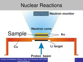
Setup • The detectors were placed in a vacuum chamber with a radioactive source. (241Am and 228Th were used) • The distance between the source and the detector was approx 25cm for 241Am and 10cm for 228Th
Two masks were used to cover the detectors. Calibration Masks
Without resistive strip: With resistive strip: Position Reconstruction 200mm Position reconstruction of impinging alpha particles for the 200 mm thick detector with and without a resistive strip.
Without mask: Slit mask: Holes mask: Position Reconstruction 400 mm Position reconstruction of impinging alpha particles with and without a mask for the 400 mm thick detector with a resistive strip.
Energy Resolution • Energy Spectrum of alpha decay from 228Th with 400mm detector: Energy Resolution: Approx 10%
Results • The position resolution was determined to be around 3-4 mm and energy resolution of 8% for both the 400 mm and 200 mm thick detectors with the resistive strip. • The resistive strip has a major contribution in reducing the position reconstruction distortion.* *For more information see T.Doke et.al. NIM A261 (1987) 605
Conclusion • The position resolution for the tetra-lateral PSDs strongly depends on the resistivity of the resistive sheet, electrode termination resistors, the filter components of the preamplifiers, and the shaping times of the amplifiers. • The measurements done were employing the use of Indiana University preamplifiers and CAEN amplifiers (3 ms shaping time). Further investigation of these dependencies is ongoing.
Acknowledgements Special thanks to: • Dr. Robert Tribble • Dr. Livius Trache • Dr. Adriana Banu • Matthew McCleskey