Download
1 / 17
170 likes | 281 Views
Interrupts , and Low-Power Modes. Interrupts.

E N D
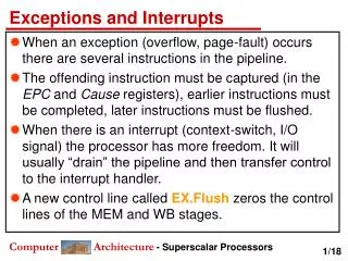
Interrupts • They are like functions but with the critical distinction that they are requested by hardwareat unpredictable times rather than called by software in an orderly manner. A periodic interrupt should be highly predictable in real time, but this is not apparent to theCPU. Interrupts are commonly used for a range of applications: • Urgent tasks that must be executed promptly at higher priority than the main code. • Infrequent tasks, such as handling slow input from humans. This saves theoverhead of regular polling. • Waking the CPU from sleep. This is particularly important in the MSP430, whichtypically spends much of its time in a low-power mode and can be awakened onlyby an interrupt. ;
Interrupts • The code to handle an interrupt is called an interrupt handler or interrupt service routine(ISR). It looks like a function but there are a few crucial modifications. Thefeature that interrupts arise at unpredictable times means that an ISR must carry out itsaction and clean up thoroughly so that the main code can be resumed without error—itshould not be able to tell that an interrupt occurred. • Interrupts can be requested by most peripheral modules and some in the core of the MCU,such as the clock generator. Each interrupt has a flag, which is raised (set) when thecondition for the interrupt occurs. For example, Timer_A sets the TAIFG flag in theTACTL register when the counter TAR returns to 0. Eachflag has a corresponding enable bit, TAIE in this case. Setting this bit allows the module torequest interrupts. • Most interrupts are maskable, which means that they are effective only if the generalinterrupt enable (GIE) bit is set in the status register (SR). They are ignored if GIE is clear.Therefore both the enable bit in the module and GIE must be set for interrupts to begenerated. The nonmaskable interrupts cannot be suppressed by clearing GIE.
Interrupts • The MSP430 uses vectored interrupts, which means that the address of each ISR—itsvector—is stored in a vector table at a defined address in memory. In most cases eachvector is associated with a unique interrupt but some sources share a vector. • Each interrupt vector has a distinct priority, which is used to select which vector is taken ifmore than one interrupt is active when the vector is fetched. The priorities are fixed inhardware and cannot be changed by the user. They are given simply by the address of thevector: A higher address means a higher priority. • The reset vector has address 0xFFFE,which gives it the top priority, followed by 0xFFFC for the single nonmaskable interruptvector. The vectors for the maskable interrupts depend on the peripherals in a particulardevice and are listed in a table of Interrupt Vector Addresses in the data sheet. As an example, the vector for theaddress 0xFFF2 has a higher priority than the shared vector ofaddress of0xFFF0.
Interrupts • Interrupts must be handled in such a way that the code that was interrupted can be resumedwithout error. This means in particular that the values in the CPU registers must berestored. The hardware can take two extreme approaches to this: • Copies of all the registers are saved on the stack automatically as part of theprocess for entering an interrupt. The disadvantage is the timerequired, which means that the response to an interrupt is delayed. An alternative isto switch to a second set of registers. • The opposite approach is for the hardware to save only the absolute minimum,which is the return address in the PC as in a subroutine. This is much faster but it isup to the user to save and restore values of the critical registers, notably the statusregister. • The MSP430 is close to the second extreme but stacks both the return address and thestatus register. The SR gets this privileged treatment because it controls the low-powermodes and the MCU must return to full power while it processes the interrupt.The otherregisters must be saved on the stack and restored if their contents are modified in the ISR.
When an Interrupt Is Requested • A lengthy chain of operations lies between the cause of a maskable interrupt and the startof its ISR. It starts when a flag bit is set in the module when the condition for an interruptoccurs. For example, TAIFG is set when the counter TAR returns to 0. This is passed to thelogic that controls interrupts if the corresponding enable bit is also set, TAIE in this case.The request for an interrupt is finally passed to the CPU if the GIE bit is set. Hardwarethen performs the following steps to launch the ISR: • Any currently executing instruction is completed if the CPU was active when theinterrupt was requested. MCLK is started if the CPU was off. • The PC, which points to the next instruction, is pushed onto the stack. • The SR is pushed onto the stack. • The interrupt with the highest priority is selected if multiple interrupts are waitingfor service. • The interrupt request flag is cleared automatically for vectors that have a singlesource. Flags remain set for servicing by software if the vector has multiplesources.
When an Interrupt Is Requested • The SR is cleared, which has two effects. First, further maskable interrupts aredisabled because the GIE bit is cleared; nonmaskable interrupts remain active.Second, it terminates any low-power mode. • The interrupt vector is loaded into the PC and the CPU starts to execute theinterrupt service routine at that address. • This sequence takes six clock cycles in the MSP430 before the ISR commences. The position of SR on the stack is important if thelow-power mode of operation needs to be changed. • The delay between an interrupt being requested and the start of the ISR is called thelatency. If the CPU is already running it is given by the time to execute the currentinstruction, which might only just have started when the interrupt was requested, plus thesix cycles needed to execute the launch sequence. This should be calculated for the slowestinstruction to get the worst case. Format I instructions take up to 6 clock cycles so theoverall latency is 12 cycles. The time required to start MCLK replaces the duration of thecurrent instruction if the device was in a low-power mode.
When an Interrupt Is Requested • The delay varies on eachoccasion because the interrupt may be requested at different points during an instruction,whose length may also differ. Thus there is no fixed interval between the request of aninterrupt and the start of its ISR. • An interrupt service routine must always finish with the special return from interruptinstruction reti, which has the following actions: • The SR pops from the stack. All previous settings of GIE and the mode control bitsare now in effect, regardless of the settings used during the interrupt serviceroutine. In particular, this reenables maskable interrupts and restores the previouslow-power mode of operation if there was one. • The PC pops from the stack and execution resumes at the point where it wasinterrupted. Alternatively, the CPU stops and the device reverts to its low-powermode before the interrupt. • This takes a further five cycles in the MSP430. The stack is restored to its state before theinterrupt was accepted.
Interrupt Service Routines • Interrupt Service Routines in Assembly Language • An ISR looks almost identical to a subroutine but with two distinctions: • The address of the subroutine, for which we can use its name (a label on its firstline), must be stored in the appropriate interrupt vector. • The routine must end with reti rather than ret so that the correct sequence ofactions takes place when it returns. • The other change in the program is that interrupts must be enabled or nothing happens.
Interrupt Service Routines • Interrupt Service Routines in C • An interrupt service routine cannot be written entirely in standard C because there is noway to identify it as an ISR rather than an ordinary function. Some extensions are therefore needed and these inevitably differbetween compilers. • Two additions areneeded to the ISR. • First is the #pragma line, which associates the function with aparticular interrupt vector. • The second is the __interrupt keyword at the beginning ofthe line that names the function. This ensures that the address of the function is stored inthe vector and that the function ends with reti rather than ret. • An intrinsic function is needed to set the GIE bit and turn on interrupts. This iscalled __enable_interrupt(), singular rather than plural.
Issues Associated with Interrupts • Follow a few simple rules toavoid some of the difficulties. • Keep Interrupt Service Routines Short: Other interrupts, which may be urgent, are disabled during an ISR unless you choose toallow nested interrupts. If lengthy processing is necessary, do the minimum in the ISR andsend a message to the main function, perhaps by setting a flag. The main function can thendo the time-consuming work between interrupts. • Configure Interrupts Carefully: Make sure that unwanted interrupts are disabled. This should be the case by default and aproblem is likely to arise only if an interrupt has been used at one time but not requiredlater. Sometimes theflag can become set before interrupts are wanted so it should be cleared before the enablebit is set. Do not set the GIE bit until you are ready to handle interrupts. • Define All Interrupt Vectors: It is good practice for safety to fill all the defined entries of the vector table, even forinterrupts that are not used. • The Shared Data Problem: It arises when variables are used both in the mainfunction and in ISRs.
Low-Power Modes of Operation • The MSP430 was designed from the outset for low power and this is reflected in a rangeof low-power modes of operation. • Active mode: Nothing is turned off (except maybe individual peripheral modules). No power savings. CPU, all clocks, and enabled modules are active. TheMSP430 starts up in this mode, which must be used when the CPU is required. Aninterrupt automatically switches the device to active mode. • LPM0 - CPU and MCLK are disabled while SMCLK and ACLK remain active. • LPM1 - CPU and MCLK are disabled, and DCO isdisabled if the DCO is not used forSMCLK. ACLK is active • LPM2- CPU, MCLK, SMCLK, DCO are disabled. ACLK is active. • LPM3 - CPU, MCLK, SMCLK, DCO are disabled, ACLK is active. • LPM4 - CPU and all clocks disabled.
Low-Power Modes of Operation • It is common to describe a device as sleeping when it is in a low-power mode, althoughthis is a little vague in the MSP430 with its range of modes. Similarly, waking means thatthe device returns to active mode. • Once parts of the microcontroller are shut off, they will not operate until specificallyturned on again. However, we can exit a low power mode (and turn these parts back on), and interrupts are extremelyuseful in this respect. • The location in SR is vital because it means that any low-power mode is suspendedautomatically when an interrupt is accepted. The current SR is stacked and the SR iscleared for the interrupt service routine, including the low-power bits (except SCG0 insome families). The low-power mode is resumed at the end of the ISR when SR is restoredfrom the stack. • We usually enter a low power mode with the interrupts enabled. If we don’t, we will not be able to wake up thesystem.The x represents LPMs from 0 to 4. __bis_SR_register(), _BIS_SR(GIE|LPM3_bits)
Waking from a Low-Power Mode • An interrupt is needed to awaken the MSP430. The processor handles an interrupt from alow-power mode in almost the same way as in active mode. The only difference is thatMCLK must first be started so that the CPU can handle the interrupt; this replaces thefirst step when the CPU is active, which is to complete the current instruction. MCLK isstarted automatically by the hardware for servicing interrupts and requires no interventionfrom the programmer. Remember that the status register is cleared when an interrupt isaccepted, which puts the processor into active mode. Similarly, MCLK is automaticallyturned off at the end of the ISR if the MSP430 returns to a low-power mode when thestatus register is restored. • We must exit the low power mode in the interrupthandler. This is done with the following code: __bic_SR_register_on_exit()