Download
1 / 21
310 likes | 610 Views
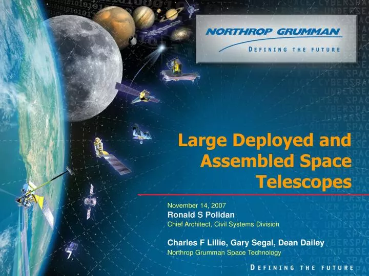
Large Deployed and Assembled Space Telescopes. November 14, 2007 Ronald S Polidan Chief Architect, Civil Systems Division Charles F Lillie, Gary Segal, Dean Dailey Northrop Grumman Space Technology. Agenda. Expectations Deployable Observatories Very Large Observatories Technology Needs.

E N D
Large Deployed and Assembled Space Telescopes November 14, 2007 Ronald S Polidan Chief Architect, Civil Systems Division Charles F Lillie, Gary Segal, Dean Dailey Northrop Grumman Space Technology
Agenda • Expectations • Deployable Observatories • Very Large Observatories • Technology Needs
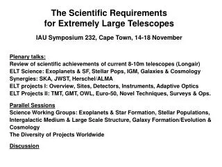
Astrophysics Beyond 2020 – Expectations • JWST will have launched in 2013, fulfilled its 5 year prime mission and be on its way to its 10-year lifetime goal • New “infrastructure” elements and technologies are changing the architectural approaches to big space telescopes • Bigger launch vehicles: EELV Heavy and Ares V • Advanced optics technology (ultra-light weight mirrors, replication, improved wavefront sensing and control technologies, …) • Advanced deployment and assembly (robotic or crewed) technologies • Linearly extrapolating from the past: • Hubble (1990): 2.4 m aperture, 11,110 kg total mass, $4.1 B (FY06, A-D) • JWST (2013): 6.5 m aperture, 6,200 kg total mass, $3.5 B (FY06, A-D) • For a similar cost we should expect to produce a ~20 m telescope, launching in the mid-2020s • Assuming anything faster than linear technology development produces 25 meter or larger filled aperture telescopes 20-m or Larger Filled Aperture Telescopes Should be Expected in the 2020’s
Fixed Width Aft Membrane Momentum Trim Flap Aft UPS Bipod Launch Lock Attachment Points Fixed Fwd and Aft Spreader Bars Fixed Side Spreader Bars Core Area MomentumTrim Flap Note: S/C Solar Array and Radiator Shades Shown in Stowed Positions for Clarity TelescopicSide Booms PM Deployment Cool Down Solar Arrays HGA Sunshield SMSS Deployment Tower Ext. Secondary Deployment Unitized Pallet Structures (UPS) Current State of the Art: JWST
Simplest Approach: Scaling Up JWST • Scaling up JWST to large EELV and Ares V launch vehicles • Lowest cost option: a JWST “rebuild” with no new technology development • Use identical cord fold deployment & sunshield architecture and technology • The bottom line for several reasons but mostly having to do with vertical height in the faring (a high center of gravity, load paths and acoustic loads are additional complications) limits you to • ~ 8 meter aperture for the largest EELV • ~ 12 meter aperture for an Ares V • For truly large telescopes, we need something more advanced than a cord fold approach
Relative Risk & Cost vs Primary Diameter Hubble Spitzer Manufacturing, Launch & Deployment Risk and Cost JWST 1 2 3 4 5 6 7 8 9 10 11 12 Stacked Hex Fan-Fold Chord-Fold Monolith Primary Mirror Diameter (m) Shift to a Family of Deployment Options Recent analysis driven by the proliferation of diverse missions requiring both large and smaller telescopes have shown that the choice of deployment approach will depend on: • Size of the primary mirror required for the mission • Launch constraints • Total mass • Launch environment • Required telescope agility • Fixed targets or • Imaging while tracking • Applicable and available mirror technology • Need smaller, stiffer segments • Availability of larger, ultra-light segments • Acceptable cost and risk
Telescope Deployment Architecture Approach Should be Optimized for Cost and Mission Needs Chord-Fold Deployment Depending on manufacturability of segments Depending on segment size & Mission Rqmts 2m - 18 Segment PM, 2m Fairing 2m - 7 Segment PM, 2m Fairing 3m - 7 Segment PM, 3m Fairing Fan-Fold Deployment Robotic Deployment Scalable to Very Large Diameters 3m - 10 Segment PM, 2m Fairing 4m - 10 Segment PM, 2m Fairing 3m - 7 Segment PM, 2m fairing
1m Segments 3m SMD Primary 2m Segments 6m Primary 3m Segments 8.5m Primary 3.5m Segments 10.5m Primary 2m Segments 10m Primary 3.5m Segments 24.5m Primary Scaling in Segment Size Hybrid Mirror Scaling in Number of Rings Advantages of Stacked Hex Deployment • Scalability to very larger telescopes • Most efficient packaging • No outboard mechanisms allowing minimal shroud diameter • Minimal additional structure required for launch • Tripod secondary support contributes to PM stiffness • Heritage concept with hardware implementation experience Scaling to Very Large Apertures One of our long term goals has been the development of an efficient deployment approach that would scale to very large telescopes ● ● ● SMD (3m) 6m UV/Vis/IR 28m UV/Vis/IR SAFIR (10m)
Far infrared wavelength detection requires ~ 4 deg K cooling 10 meter, 7 hex segment deployment scheme • Positioning boom • Deploys and positions scope • Thermally decouples scope from sunshield • Very low frequency, highly damped jitter isolation • Maintains balance between mass and pressure centers over large F.O.R. New telescope payload JWST bus subsystem re-use Stowed in EELV 5 m heavy (Restraint shell removed for clarity) Lower frequency telescope attachments provide greater observatory flexibility and performance! SAFIR Observatory Concept
Stack Deployment Animation • Application of NGST High Accuracy Reflector Deployment System (1990)
Thermal And Dynamic Isolation Boom • Thermal and dynamic isolation boom concept with fine pointing • Produces ~3 Pi steradian instantaneous field of regard • Allows for improved momentum management by control of CP/CG
Conical “Sugar Scoop” Flat Advanced Sunshield Approaches • The level of thermal stability being demanded by future big telescope missions preclude the use of simple sunshields • Need to look toward multi-layer or possibly active sunshields • These too will need to be deployed
Scaling to Very Large Apertures • Long standing analysis and design confirms that deployment of stacked, Hex segments provides the most efficient approach to scaling to large telescope apertures • Two basic approaches to scaling segmented telescopes: Scale the number of deployed rings Issues • Deployment of large number of segments • Largest number of rigid body actuators • Highest weight ratio • Highest number of segment prescriptions Issues • Highest risk of manufacturability of very large segments • Requires largest faring diameter Scale the size of the segments
30-m spherical primary mirror telescope Secondary (f/d = 1.79) 30 meter spherical primary mirror Spherical corrector assembly Spherical corrector assembly
30 m Assembled Spherical Telescope concept Bus and telescope rendezvous and dock here
30 M Spherical Telescope Observatory Concept • Five EELV heavy launches • Total lift capability ~ 40,000 Kg’s • Observatory SWAG ~ 27,000 Kg’s • Weight margin ~ 48%
On-orbit Servicing Courtesy of Jack Frassanito & Associates and Dr. Harley Thronson
Nonolaminate on Mandrel Image Plane & WFS&C Sensor Model Sensor Imaging FPA (4096 X 4096 8mm pixels) Scene Tracker Focal Plane Fine Figure & Phase Sensor Beam Footprint at FPA Plane Key Technologies Enabling Next Generation Space Telescopes • Rapid, low cost fabrication of ultra-light weight primary mirror segments • Eliminates time consuming grinding and polishing • Several approaches including vapor deposition of nanolaminates bonded to actuated substrates • Active figure control of primary mirror segments • High precision actuators • Surface parallel actuation eliminates need for stiff reaction structure (SMD) • High speed wavefront sensing and control • High density figure control enables very light weight mirror segments • High speed, active while imaging WFS&C allows for rapid slew and settle and earth imaging • Highly-packageable & scalable deployment techniques • Deployment architecture should take advantage of light weight mirrors • Active control for light weight structural elements to supply good stability • Reduces weight required for vibration and thermal control
Conclusions • Space telescopes with 20-meter and larger apertures are within affordable reach by the mid-2020’s • To achieve this we need to initiate a technology development plan that thoroughly explores the trade options and identifies and matures the enabling technology • We need the sustained technology development funding to mature the technology