Download
1 / 28
280 likes | 826 Views
Chapter Three 80x86 Microprocessor 80x86 微处理器 ( 4 ). 8086 Segment Registers.

E N D
Chapter Three80x86 Microprocessor80x86微处理器(4) 2014年3月12日1
8086 Segment Registers • The 8086 has four special segment registers: cs, ds, es, and ss. These stand for Code Segment, Data Segment, Extra Segment, and Stack Segment, respectively. These registers are all 16 bits wide. They deal with selecting blocks (segments) of main memory. A segment register (e.g., cs) points at the beginning of a segment in memory.(???) • Segments of memory on the 8086 can be no larger than 65,536 bytes long. This infamous “64K segment limitation” has disturbed many a programmer. We’ll see some problems with this 64K limitation, and some solutions to those problems, later. 2014年3月12日2
8086 Segment Registers • The cs register points at the segmentcontaining the currently executing machine instructions. • The data segment register, ds, generally points at global variables for the program. • The extra segment register, es, is exactly that – an extra segment register. • The ss register points at the segment containing the 8086 stack. The stack is where the 8086 stores important machine state information, subroutine return addresses, procedure parameters, and local variables. In general, you do not modify the stack segment register because too many things in the system depend upon it. 2014年3月12日3
8086 Segment Registers • Although it is theoretically possible to store data in the segment registers, this is never a good idea. The segment registers have a very special purpose – pointing at accessible blocks of memory. Any attempt to use the registers for any other purpose may result in considerable grief. 2014年3月12日4
8086 Special Purpose Registers • There are two special purpose registers on the 8086 CPU: the instruction pointer (ip) and the flags register. You do not access these registers the same way you access the other 8086 registers. Instead, the CPU generally manipulates these registers directly. • The ip register contains the address of the currently executing instruction. This is a 16 bit register which provides a pointer into the current code segment (16 bits lets you select any one of 65,536 different memory locations). We’ll come back to this register when we discuss the control transfer instructions later. 2014年3月12日5
8086 Special Purpose Registers • The flags register is unlike the other registers on the 8086. The other registers hold eight or 16 bit values. The flags register is simply an collection of one bit values which help determine the current state of the processor. Although the flags register is 16 bits wide, the 8086 uses only nine of those bits. Of these flags, four flags you use all the time: zero, carry, sign, and overflow. These flags are the 8086 condition. 2014年3月12日6
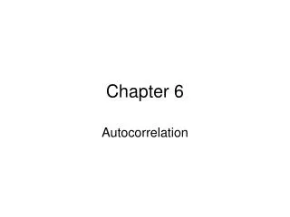
EEE/CSE 226 Address 0H Segment Starting address is segment register value shifted 4 places to the left. CODE 64K Data Segment STACK DATA EXTRA CS:0 64K Code Segment Segment Registers Segments are < or = 64K, can overlap, start at an address that ends in 0H. 0FFFFFH MEMORY I-14 2014年3月12日7
8086 Memory Terminology Memory Segments Segment Registers 0H 01000H DATA DS: 0100H 10FFFH 0B2000H SS: 0B200H STACK 0C1FFFH ES: 0CF00H 0CF000H EXTRA 0DEFFFH 0FF00H CS: 0FF000H CODE 0FFFFFH Segments are < or = 64K and can overlap. Note that the Code segment is < 64K since 0FFFFFH is the highest address. 2014年3月12日8 I-15
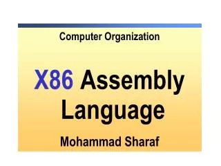
0H The Code Segment 4000H CS: 0400H 4056H IP 0056H CS:IP = 400:56 Logical Address Memory 0400 0 Segment Register Offset Physical or Absolute Address + 0056 0FFFFFH 04056H The offset is the distance in bytes from the start of the segment. The offset is given by the IP for the Code Segment. Instructions are always fetched with using the CS register. The physical address is also called the absolute address. 2014年3月12日9 I-16
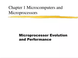
0H The Stack Segment 0A000H 0A00 SS: 0A100H SP 0100 SS:SP Memory 0A00 0 Segment Register Offset Physical Address + 0100 0FFFFFH 0A100H The offset is given by the SP register. The stack is always referenced with respect to the stack segment register. The stack grows toward decreasing memory locations. The SP points to the last or top item on the stack. PUSH - pre-decrement the SP POP - post-increment the SP 2014年3月12日10 I-17
0H The Data Segment 05C00H 05C0 DS: 05C50H 0050 EA DS:EA Memory 05C0 0 Segment Register Offset Physical Address + 0050 0FFFFFH 05C50H Data is usually fetched with respect to the DS register. The effective address (EA) is the offset. The EA depends on the addressing mode. 2014年3月12日11 I-18
控制寄存器 IP(Instruction Pointer)——指令指针寄存器。用来存放下一条要读取的指令在代码段内的偏移地址。用户程序不能直接访问IP。 FLAGS——标志寄存器。它是一个16位的寄存器,但只用了其中9位,这9位包括6个状态标志位,3个控制标志位,如图3.5所示。 2014年3月12日12
图3.5 8086/8088的标志寄存器 2014年3月12日13
1. 状态标志位(6位) 状态标志位用来反映算术和逻辑运算结果的一些特征。下面分别介绍这6个状态标志位的功能。 CF(Carry Flag)——进位标志。当进行加减运算时,若最高位发生进位或借位则CF为1,否则为0。通常用于判断无符号数运算结果是否超出了计算机所能表示的无符号数的范围。 PF(Parity Flag)——奇偶标志位。当指令执行结果的低8位中含有偶数个1时,PF为1,否则为0。 2014年3月12日14
AF(Auxiliary Flag)——辅助进位标志位。当执行一条加法或减法运算指令时,若结果的低字节的低4位向高4位有进位或借位,则AF为1,否则为0。 ZF(Zero Flag)——零标志位。若当前的运算结果为0,则ZF为1,否则为0。 SF(Sign Flag)——符号标志位。当运算结果的最高位为1时,SF=1,否则为0。 OF(Overflow Flag)——溢出标志位。当运算结果超出了带符号数所能表示的数值范围,即溢出时,OF=1,否则为0。用来判断带符号数运算结果是否溢出。 2014年3月12日15
+ 15 14 13 12 11 10 9 8 7 6 5 4 3 2 1 0 O D I T S Z A P C 1 1 0 1 1 0 0101 0100 0011 1001 + 0100 0101 0110 1010 1001 1001 1010 0011 最高位 = 1 SF=1 低 8 位中偶数为 4 个 PF=1 运算结果不为 0 ZF=0 低 4 位向前有进位 AF=1 最高位向前没有进位 CF=0 次高位向前有进位 Cs=0,Cp=1,OF=Cs Cp=1 2014年3月12日16
11101111 +) 11001000 10110111 0101101000001010 0100110010100011 1010011010101101 1 DF=1 DF=1 CF=1 CF=0 自动丢失 例3.1设变量x=11101111B,y=11001000B,X=0101101000001010B,Y=01001100 10100011B,请问分别执行x+y和X+Y操作后标志寄存器中各状态位的状态如何? 2014年3月12日17
状态位 执行x+y后 执行X+Y后 CF 最高位D7向前有进位,CF=1 最高位D15向前没有进位,CF=0 PF 低8位中1的个数为偶数(6),PF=1 低8位中1的个数为奇数(5),PF=0 AF 低4位向前有进位,AF=1 低4位向前没有进位,AF=0 ZF 计算结果不为0,ZF=0 计算结果不为0,ZF=0 SF 最高位D7为1,SF=1 最高位D15为1,SF=1 OF CFDF=0,没有溢出,OF=0 CFDF=1,结果溢出,OF=1 2014年3月12日18
2. 控制标志位(3位)——用来控制CPU的操作,由程序设置或清除。它们是: TF(Trap Flag)——跟踪(陷阱)标志位。是为测试程序的方便而设置。若将TF置1,CPU处于单步工作方式。 IF(Interrupt Flag)——中断允许标志位。是用来控制可屏蔽中断的控制标志位。若将IF置1,表示允许CPU接受外部从INTR引脚上发来的可屏蔽中断请求;若用CLI指令将IF清0,则禁止CPU接受可屏蔽中断请求信号。 DF(Direction Flag)——方向标志位。若将DF置1,串操作按减地址方式进行,也就是说,从高地址开始,每操作一次地址自动递减;否则按增地址方式进行。 2014年3月12日19
注意 有关寄存器,尤其是在存储器寻址时用来存放操作数在段内偏移地址的地址寄存器和标志寄存器中各控制标志位的使用方法,将在后续章节中涉及到时还将进一步详细介绍,请读者务必熟练掌握。 2014年3月12日20
8088CPU与8086CPU的异同 二者内部结构基本相似,执行单元EU完全相同,其指令系统、寻址方式及程序设计方法都相同。区别仅在于总线接口单元BIU,归纳起来主要有以下几个方面的差异: 1.外部数据总线位数不同。8086外部数据总线16位,8088外部数据总线8位。 2.指令队列缓冲器大小不同。8086指令队列可容纳6个字节;而8088指令队列只能容纳4个字节。 3. 部分引脚的功能定义有所区别。 2014年3月12日21
Pinouts See Fig 7-2 in textbook and Appendix A. 2014年3月12日22
The 8086 comes in a 40 pin package which means that some pins have • more than one use or are multiplexed. The packaging technology of time • limited the number of pin that could be used. • In particular, the address lines 0 - 15 are multiplexed with data lines 0-15, • address lines 16-19 are multiplexed with status lines. These pins are • AD0 - AD15, A16/S3 - A19/S6 • The 8088 does not have the upper 8 data lines so the pins are A8 - A15. • The 8086 has one other pin that is multiplexed and this is BHE’/S7. • BHE stands for Byte High Enable. This is an active low signal that is • asserted when there is data on the upper half of the data bus. There is no • need for this signal on an 8088. • The 8086 has two modes of operation that changes the function of some pins. • The SDK-86 uses the 8086 in the minimum mode with the MN/MX’ pin tied to • 5 volts. This is a simple single processor mode. The IBM PC uses an 8088 • in the maximum mode with the MN/MX” pin tied to ground. This is the mode • required for a coprocessor like the 8087. 2014年3月12日23
In the minimum mode the following pins are available. • HOLD When this pin is high, another master is requesting control of the • local bus, e.g., a DMA controller. • HLDA HOLD Acknowledge: the 8086 signals that it is going to float • the local bus. • WR’ Write: the processor is performing a write memory or I/O operation. • M/IO’ Memory or I/O operation. • DT/R’ Data Transmit or Receive. • DEN’ Data Enable: data is on the multiplexed address/data pins. • ALE Address Latch Enable: the address is on the address/data pins. • This signal is used to capture the address in latches to establish the • address bus. • INTA’ Interrupt acknowledge: acknowledges external interrupt requests. 2014年3月12日24
The following are pins are available in both minimum and maximum modes. • VCC + 5 volt power supply pin. • GND Ground • RD’ READ: the processor is performing a read memory or I/O operation. • READY Acknowledgement from wait-state logic that the data transfer will • be completed. • RESET Stops processor and restarts execution from FFFF:0. Must be high • for 4 clocks. CS = 0FFFFH, IP = DS = SS = ES = Flags = 0000H, no • other registers are affected. • TEST’ The WAIT instruction waits for this pin to go low. Used with 8087. • NMI Non Maskable Interrupt: transition from low to high causes an • interrupt. Used for emergencies such as power failure. • INTR Interrupt request: masked by the IF bit in FLAG register. • CLK Clock: 33% duty cycle, i.e., high 1/3 the time. 2014年3月12日25
Timing Figure 7-1(b) of Textbook 2014年3月12日26
第3章中文作业 中文教材: P84 1 2 3 9 2014年3月12日27
第3章英文作业 1. Convert the following logical addresses to physical addresses. Assume all values are hexadecimal: a) 1000:1000 b) 1234:5678 c) 0:1000 d) 100:9000 e) FF00:1000 f) 800:8000 g) 8000:800 h) 234:9843 i) 1111:FFFF j) FFFF:10 2. Besides memory addressing modes, what are the other two major addressing modes on the 8086? 3. Give an example for each of the following addressing modes: a) Register b) Immediate c) Displacement only d) Register Indirect e) Based indexed f) Based indexed plus displacement 4. List all of the 8086 eight bit registers. 5. List all the 8086 general purpose 16 bit registers, and describe the “special purposes” of each of the general purpose registers. 6. List all the 8086 segment registers. 2014年3月12日28