Download
1 / 41
410 likes | 590 Views
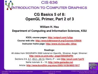
Introduction to 3D Graphics Lecture 4: Scenes and Scene Graphs. Anthony Steed University College London. No More Spheres!. Overview. Polygons Representation Intersection Polyhedra Face sets Winged edge Scene graphs. Polygons. A polygon (face) Q is defined by a series of points

E N D
Introduction to 3D GraphicsLecture 4: Scenes and Scene Graphs Anthony Steed University College London
Overview • Polygons • Representation • Intersection • Polyhedra • Face sets • Winged edge • Scene graphs
Polygons • A polygon (face) Q is defined by a series of points • The points are must be co-planar • 3 points define a plane, but a 4th point need not lie on that plane
Types of Polygon • Simple - Concave, Convex • Complex We like simple, concave polygons since they are easy to break into triangles
Equation of a Plane • a,b,c and d are constants that define a unique plane and x,y and z form a vector P.
p 2 p 1 p p 0 Deriving a,b,c & d (1) • The cross product defines a normal to the plane • There are two normals (they are opposite) • Vectors in the plane are all orthogonal to the plane normal vector
Deriving a,b,c & d (2) • So p-p0 is normal to n therefore • But if n = (n1,n2,n3) • a= n1 b= n2 c= n3 (n.p) • d = n.p0 = n1*x0 + n2*y0 + n3*z0
Half-Space • A plane cuts space into 2 half-spaces • Define • If l(p) =0 • point on plane • If l(p) > 0 • point in positive half-space • If l(p) <0 • point in negative half-space
Outline of Polygon Ray Casting • Three steps • Does the ray intersect the plane of the polygon? • i.e. is the ray not orthogonal to the plane normal • Intersect ray with plane • Test whether intersection point lies within polygon on the plane
Does the ray intersect the plane? • Ray eq. is p0 + t.d • Plane eq. is n.(x,y,z) = k • Then test is n.d !=0
Where does it intersect? • Substitute line equation into plane equation • Solve for t • Find pi
Is this point inside the polygon? • Many tests are possible • Winding number (can be done in 3D) • Infinite ray test (done in 2D)
Winding Number Test • Sum the angle subtended by the vertices p2 1 p1 n-1 pn-1
Inside and Outside • Not just draw (stroke, fill) • For closed Shapes • Hit test - inside or outside based on a winding rules (non-zero or even-odd)
Counting Edge Crosses • Draw a line from the test point to the outside • Count +1 if you cross an edge in an anti-clockwise sense • Count -1 if you cross and edge in a clockwise sense -1 +1
Overview • Polygons • Representation • Intersection • Polyhedra • Face sets • Winged edge • Scene graphs
Polyhedra • Polygons are often grouped together to form polyhedra • Each edge connects 2 vertices and is the join between two polygons • Each vertex joins 3 edges • No faces intersect • V-E+F=2 • For cubes, tetrahedra, cows etc...
Example Polhedron v 4 e7 • F0=v0v1v4 • F1=v5v3v2 • F2=v1v2v3v4 • F3=v0v4v3v5 • F4=v0v5v2v1 • V=6,F=5, E=9 • V-E+F=2 v 3 e9 e5 e6 e8 v 5 e3 v 2 e4 e2 v o v 1 e1
Representing Polyhedron (1) • Exhaustive (array of vertex lists) • faces[1] = (x0,y0,z0),(x1,y1,z1),(x3,y3,z3) • faces[2] = (x2,y2,z2),(x0,y0,z0),(x3,y3,z3) • etc …. • Very wasteful since same vertex appears at 3(or more) points in the list • Is used a lot though!
Representing Polyhedron (2) • Indexed Face set • Vertex array • vertices[0] = (x0,y0,z0) • vertices[1]=(x1,y1,z1) • etc … • Face array (list of indices into vertex array) • faces[0] = 0,2,1 • faces[1]=2,3,1 • etc ...
Vertex order matters • Polygon v0,v1,v4 is NOT equal to v0,v4,v1 • The normal point in different directions • Usually a polygon is only visible from points in its positive half-space • This is known as back-face culling • Polygon v0,v1,v4 is NOT equal to v0,v4,v1 • The normal point in different directions • Usually a polygon is only visible from points in its positive half-space • This is known as back-face culling v v 4 4 v v 3 3 v v 5 5 v 2 v v o o v v 1 1
Representing Polyhedron (3) • Even Indexed face set wastes space • Each face edge is represented twice • Winged edge data structure solves this • vertex list • edge list (vertex pairs) • face list (edge lists)
The Edge List Structure N C C W ( e ) P C W ( e ) • Edge contains • Next edge CW • Next edge CCW • Prev edge CW • Prev edge CCW • Next face • Prev face • Next vertex • Prev vertex P V ( e ) e N F a c e ( e ) P F a c e ( e ) N V ( e ) P C C W ( e ) N C W ( e )
Advantages of Winged Edge • Simple searches are rapid • find all edges • find all faces of a vertex • etc… • Complex operations • polygon splitting is easy (LOD) • silhouette finding • potentially efficient for hardware • etc…
Building the WE • Build indexed face set • Traverse each face in CCW order building edges • label p and n vertices, p and n faces and link previous CCW edge • we fill in next CCW on next edge in this face • we fill in next CW and prev CW when traversing the adjacent face.
Overview • Polygons • Representation • Intersection • Polyhedra • Face sets • Winged edge • Scene graphs
Concept of Scene Graph • Objects placed relative to one another • Objects made of similar components • Directed acyclic graph root
Use for Animation/Modelling H F E U S B
One object has a local transformation relative to its parent • shoulder is translation (0 1 0) from base • upper arm is translation (0 3 0) from shoulder • elbow is translation (0 3 0) from upper arm • fore arm is rotation Z by -90 then translation (0 2 0)
Rendering Traverse • Must get object definitions in WC before passing to camera • For object under Base • p.B is in WC • “inherit” matrices down stack • So for object under shoulder • p.SB is in WC • (p.S is in base coordinates)
In general • On traverse • “push” on graph descend • “pop” on graph ascend • Combined matrix is current transform (CTM)
Sharing Nodes T0 • E.G. One table many places • Table1 has CTM T1T0 • Table2 has CTM T2T0 T1 T2 table1 table2 table
Spherical Coordinates • Represent a point on a using two angles and . Where r = length(x,y,z) Z Q is projection of P onto XY plane is angle between X axis and OQ is angle between OP and Z axis P ( x , y , z ) Y j Q O q X
Spherical Coordinates • Length OQ = r sin() • So • x = r sin()cos( ) • y = r sin()sin( ) • z = r cos()
Rotation About an Arbitrary Axis Z p2 Y O p1 X
… 1. Translate p1 so it is at the origin 2. Let p3 = p2-p1 (new position of p2) find spherical co-ordinate of p3 (r, ,) 3. Rotate about Z by - to bring p3 into ZX plane 4. Rotate about Y by - to bring p3 onto Z axis 5. Now rotate about Z by 6. Invert steps 4-1
… p3 p2 Z Z Y Y O p1 O Start Translate
… p3 p3 Z Z Y Y Rotate2 Rotate1
… p3 • Now we apply the transformation we are after • Invert steps 4-1 Z Y After Steps 1-4
Summary • Established a set of techniques for describing scenes made of polygons • Particularly the roles of local-coordinates, which form the modelling matrix stack in OpenGl • Described how to ray-cast these shapes • The mathematics of this will be crucial when we turn to projection next week.