Download
1 / 14
140 likes | 210 Views
GEOMETRIC DESCRIPTION OF THE ROBOT MECHANISM. T. Bajd and M. Mihelj. Robot mechanism with coordinate frames.

E N D
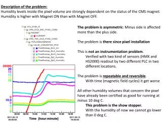
GEOMETRIC DESCRIPTION OF THE ROBOT MECHANISM T. Bajd and M. Mihelj
Robot mechanism with coordinate frames The geometric description of the robot mechanism is based on the usage of translationaland rotational homogenous transformation matrices. A coordinate frame isattached to the robot base and to each segment of the mechanism. Vector expressed in one of the frames can be transformed into another frame by successive multiplication of intermediate transformation matrices.
Vector parameters of kinematic pair • Vector parameters for geometric description of a robot mechanism. • Consider only mechanisms with parallel or perpendicular consecutive joint axes. • Segments i−1 and iconnected by joint iincluding both translation and rotation. • Relative pose of the joint determined by the segment vector bi−1and unit joint vector ei • Segment ican be • translated along the vector eifor the distance diand • rotated around eifor the angle ϑi.
Geometric relations and relative displacement • ei– unit vector describing either the axis of rotation or direction of translation inthe joint iand is expressed as one of the axes of the xi, yi, ziframe • bi−1 – segment vector describing the segment i−1 expressed in the xi−1, yi−1,zi−1frame • ϑi– rotational variable representing the angle measured around the eiaxis in theplane which is perpendicular to ei(the angle is zero when the kinematic pair isin the initial position); • di– translational variable representing the distance measured along the directionof ei(the distance equals zero when the kinematic pair is in the initial position).
Rotational and translational joint • Rotational joint • variable is angle ϑi, • while di = 0 • Translational joint • variable is displacement di, • while ϑi = 0 • In initial pose • joint angle equals zero, ϑi = 0 • joint displacement equals zero, di = 0 • and the coordinate frames xi, yi, ziand xi−1, yi−1, zi−1 are parallel.
Joint transformation matrices • joint axis aligned with xi • joint axis aligned with yi • joint axis aligned with zi • without joint
Vector parameters in four steps • STEP 1 • robot mechanism is placed into the desired initial (reference) pose; • joint axes must be parallel to one of the axes of the reference coordinate frame x0, y0, z0; • in the reference pose all values of joint variables equal zero, ϑi= 0 and di= 0, i= 1,2, ...,n; • STEP 2 • centers of the joints i=1,2, ...,n are selected; • center of joint ican be anywhere along the corresponding joint axis; • local coordinate frame xi, yi, ziis placed into the joint center in such a way that its axes are parallel to the axes of the reference frame x0, y0, z0; • local coordinate frame xi, yi, ziis displaced together with the segmenti; • STEP 3 • unit joint vector eiis allocated to each joint axis i = 1,2, ...,n; • it is directed along one of the axes of the coordinate frame xi, yi, zi; • in the direction of this vector the translational variable di is measured, while the rotational variable ϑiis assessed around the joint vector ei; • STEP 4 • segment vectors bi−1are drawn between the origins of the xi, yi, ziframes, i= 1,2, ...,n; • segment vector bnconnects the origin of the xn, yn, znframe with the robot end-point.
Mechanismwith four degrees of freedom Reference pose
Joint transformation matrices Constant matrix Joint 1 Joint 2 Joint 3 Joint 4
SCARA robot mechanism Reference pose Vector parameters
Joint transformation matrices Joint 1 Joint 2 Joint 3