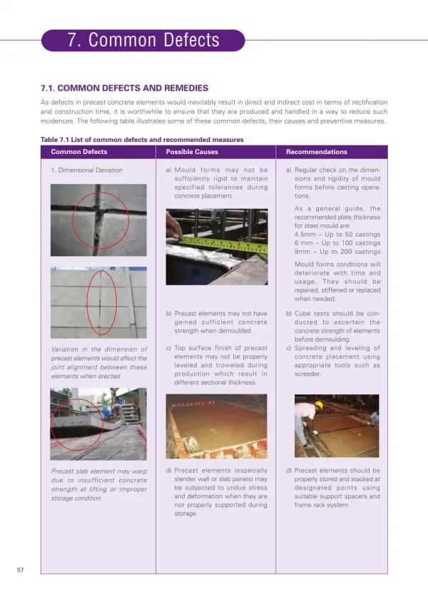
Download
1 / 24
240 likes | 396 Views
Lens Defects Many defects result from the laws of reflection and refraction. The refractive index of a lens varies with the wavelength of light, the focal length of the lens varies with the refractive index . As a results focal length will change for different colors of light.

E N D
Lens Defects • Many defects result from the laws of reflection and refraction. • The refractive index of a lens varies with thewavelength of light, • the focal length of the lens varies with the refractive index. • As a resultsfocal length will changefor different colors of light. • A separate image for each wavelength present is focused at different distances from the lenscausingLongitudinal chromatic aberration(Fig. 10). • Moreover, magnification varies withfocallength, altering the size ofthe imageresulting in lateral chromatic aberration (Fig. 11). • These aberationsmust be eliminated forcolourphotographs. Since achromatshave limited corrections for these problems, they must be used with yellow-green lightfiltering to obtain sharp images.
Fig. 10 Longitudinal chromatic aberration in an uncorrected lens. Different wavelengths cause each of the threeprimary colors to be focused at a different point along the optical axis.
Fig. 11 Lateral chromatic aberration. As focal length is varied, magnification changes, altering image size.
Spherical aberration (Fig. 12) • It occurs due to the refraction differences between the center and the periphery of the lens. • Light from an object on the optical axis is more strongly refracted at the periphery of the lens than at the centre, producing a series of focal positions where point images appear. • This can be minimized by using an aperture that restricts use of the objective to the central portion. Lens design also can correct part of this problem.
Fig. 12 Spherical aberration. Light rays passing through the outer portion of the lens are more stronglyrefracted than those passing through the central portion and are focused at a different point along the opticalaxis. This problem can be minimized by using an aperture to restrict the light path to the central part of the objective.
Fig. 13 Image distortions caused by curvature in the image surface of best focus. A compensating eyepiece,with a curvature equal to but opposite of that of the image surface, must be used to produce a normal image.
Resolution • Adequate resolution, or resolving power, and adequate image contrast is required to see microstructural detail. • Acceptability of only one of these is not enough to observe the detail. • Power of resolution is theabilitytoresolve two points or lines separated by a distance d andis a function of the wavelength, λ, of the incident light and thenumerical aperture,NA, of the objective. • where k is 0.5 or 0.61. Figure 14 illustrates this relationship for • k = 0.61 and four light wavelengths. • Equation 2 does not include other factors influencingresolution, such as the degree ofcorrection of the objectives and the visual acuity of the microscopist. • It was based on the work of Abbe under certainconditionssuch as self-luminous points, perfect black-white contrast, transmitted-light examination, anideal point-light source, and absence of lens defects (Ref 11).
Fig. 14 Relationship between the resolution possible with an incident-light microscope and the numericalaperture of the objective lens used for four wavelengths of light
The limit of resolution for an objective with an NA of 1.4 used with a green light (=0,546 m) is calculated by using Eq 2 and found approximately 0.2 μm. • This means that the two points 0,2 μm apart from each other can be observed by using this objective. But 0,2 μmis beyond the power of resolution of human eyes. Therefore the distance0,2 μm should be so magnified as to seen by the naked human eye. • The required magnification can be determined by dividing the resolving power of the objective bythe resolving power of the human eye, which is difficult to determine under observation conditions. • Abbe used a value of0.3 mm at a distance of 250 mm--the distance from the eye for optimum vision. For light with a mean wavelength of 0.55μm, the required magnification is 1100 times the NA of the objective. • This is the origin of the 1000 NA rule for themaximum useful magnification. Any magnification above 1000 NA is termed "empty," or useless.
1000 NA rule can not be strictly followed due to the fact that the reel conditions encountered in metallographic reality is far from what Abbey assumed. • Therefore It has been suggested that the upper limit of useful magnification for the average microscopist is 2200 NA, not 1000 NA (Ref 11). • Depth of Field • Depth of field is the distance along the optical axis over which image details are observed with acceptable clarity. • Those factors influencing resolution also affect depth of field, but in the opposite direction. • Therefore, a compromise must bereached between these two parameters, which becomes more difficult as magnification increases. This is one reason lightetching is preferred for high-magnification examination. The depth of field, Tf, can be estimated from:
Here λ, n and NA have the usual meaning, being wavelength, refractive indices and numerical aperture respectively. Fig. 15 Relationship among depth of field of the image produced, numerical aperture of the objective used, and wavelength of light employed
Examination Modes • To achieve the resolution capability of the selected objective, image contrast must be adequate. • Image contrast dependson specimen preparation and optics. • Differences in light reflectivity from the specimen surface produce amplitudefeatures visible to the eye after magnification. • Phase differences createdby light reflection must be rendered visible by theuse of phase-contrast or interference-contrast attachments to the microscope.
Bright-Field Illumination. • It is the most widely used method of observation, accountsfor the vast majority of micrographs taken. • In operation, light passes through the objective and strikes the specimensurface perpendicularly. • Surface features normal to the incident light reflect light back through the objective to theeyepieces, where the surface features appear bright. • Surfaces oblique to the light beam reflect less light to the objectiveand appear darker, depending on their angle.
Oblique Illumination. • It is possible to de-centerthe condenser assembly insome microscopes, or the mirror so thatthe light passing through the objective strikes the specimen surface at a non-perpendicular angle. • Roughness on thespecimen surface will cast shadows, producing a three-dimensional appearance. • This allows determinationof features thatare in relief or are recessed. • However, very little obliquenesscan be introduced, because this technique causes lighting tobecome non-uniformand reduces resolution.
Dark-field illumination, • The light reflected from obliquely oriented features is collected, • The rays reflectedfrom features normal to the incident beam are blocked. • Therefore, the contrast is essentially reversed from that of brightfieldillumination; that is, features that are bright in bright-field illumination appear dark, and features normally darkappear bright. • This produces very strong image contrast, with the oblique features appearing luminous. Under suchconditions, it is often possible to see features not visible using bright-field illumination. • This method is particularly usefulfor studying grain structures. • However, the low light intensity makes photomicroscopy more difficult, a problem lessenedby the use of automatic exposure-control devices.
Polarized light (Ref 12, 13, 14), • Its use in metallography has generally been limited forsomeopticallyanisotropic metals, such as beryllium, a-titanium, zirconium, and uranium, • Thesemetals are difficult to etch but respond well topolarized light when properly polished. • Before development of the electron microprobe analyzer (EMPA) and energydispersivespectroscopy (EDS), polarized light examination was an integral part of the procedure for identifyinginclusions. • Since the development of these instruments, polarized light has been used less frequently for this purpose,because identification with the EMPA or EDS techniques is more definitive. • Most metallurgical microscopes now use synthetic Polaroid filters. The "polarizer" is placed in the light path before theobjective, and the "analyzer" is placed in the light path after the objective, generally just below the eyepiece. • Figure 26shows the light path in the incident-light polarizing microscope.
Fig. 26 Light path in an incident-light polarizing microscope. 1, Hinged lens; 2, half stop; 3, aperturediaphragm; 4, filter or prism polarizer; 5, field diaphragm; 6, centrable lens, used to center the fielddiaphragm; 7, polished section; 8, objective; 9, compensating prism, with switchover against optical-flatreflector; 10, tube lens (intermediate optical system); 11, rotating analyzer; 12, eyepiece with focusingeyelens. (E. Leitz, Inc.)
Light vibrating in all directions at right angles to the direction of propagation passes through apolarizing filter, the vibrations occur in only one plane in the direction of propagation, and the light is termed plane-polarized. • This plane will change as the filteris rotated. • When the analyzer filter is placed in the light path, plane-polarizedlight will pass through it if the plane of vibration of the light is parallel to the plane of vibration of the analyzer.Otherwisethe light will not pass through, and extinctionresults. • When plane-polarized light is reflected from the surface of an isotropic metal (any metal with a cubic crystallographicstructure, such as iron), then passes through the analyzer in the crossed position (plane of vibration perpendicular to thatof the plane-polarized light), the image is extinguished, or dark. • However, in practice, because the metallurgicalmicroscope will not produce perfectly plane-polarized light, complete extinction will not occur. • Strain-free objectives, usuallyachromats, must be used. Fluorite or apochromatic objectives are unsuitable. A strong white-light source is required toproduceaccuratecoloreffects.
Itmay be difficult to set the polarizer and analyzer in the crossed position accurately when an anisotropicspecimen is in place unless the crossed positions are marked on the polarizer and the analyzer, • it is best to find thisposition first using an isotropic specimen. • Isotropic metals can also be examined using crossed-polarized light if only the surface can be rendered optically active by etching, staining, or anodizing.
Use of polarized light: • It is goodtoexamineinclusions, anisotropic metals (antimony, beryllium, bismuth, cadmium, cobalt,magnesium, scandium, tellurium, tin, titanium, uranium, zinc, andzirconium, forexample), andetched/anodized/tintetchedcubic metals, • polarized light is alsouseful for examination of coated or deformed metals. • Phase identification may alsobe aidedin some cases. The internal structure of graphite nodules in cast iron is vividly revealed using polarized light(Fig. 29, 30, 31). • Martensitic structures are frequently better revealed using polarized light, as shown in Fig. 32 and 33,which illustrate lath martensite in a high-strength iron-base alloy, AF 1410.
Phase contrast illumination • Application ofphase-contrast illumination in metallography has been limited. The technique requires a separate set of objectives and aspecialverticalilluminator. • Itallowsexamination of subtle phase variations in microstructures with little orno amplitude contrast from differences in the optical path at the surface (reflected light) or from differences in the opticalpath through the specimen (transmitted light). • Height differences as small as 0.005 μm can be detected.
Interference-ContrastIllumination. • Differentialinterference-contrast (DIC) illumination (Ref 17, 18, 19) producesimages with emphasized topographic detail similar to those observed using oblique illumination. • Detail that is invisible orfaintly visible using bright-fieldillumination may be revealed vividly with interference-contrast illumination.
Interference Techniques. • Several interference techniques (Ref 20, 21) are used to measure height differences onspecimens. • Interference fringes on a perfectly flat surface appear as straight, parallel lines of equal width and spacing. • Height variations cause these fringes to appear curved or jagged, depending on the unit used. • The interference microscopedivides the light from a single point source into two or more waves that are superimposed after traveling different paths. • This produces interference. Two-beam and multiple-beam instruments are the two basic types of interferometers used. • The measurements are based on the wavelength of the light used. Two-beam interferometers can measure heightdifferences as small as λ/20; multiple-beam interferometers, as small as λ/200.