Download
1 / 45
460 likes | 633 Views
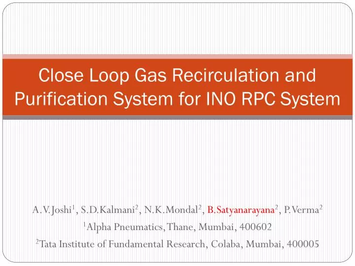
Close Loop Gas Recirculation and Purification System for INO RPC System. A.V.Joshi 1 , S.D.Kalmani 2 , N.K.Mondal 2 , B.Satyanarayana 2 , P.Verma 2 1 Alpha Pneumatics, Thane, Mumbai, 400602 2 Tata Institute of Fundamental Research, Colaba, Mumbai, 400005. INO’s 50kt magnetised ICAL detector.

E N D
Close Loop Gas Recirculation and Purification System for INO RPC System A.V.Joshi1, S.D.Kalmani2, N.K.Mondal2, B.Satyanarayana2, P.Verma2 1Alpha Pneumatics, Thane, Mumbai, 400602 2Tata Institute of Fundamental Research, Colaba, Mumbai, 400005
INO’s 50kt magnetised ICAL detector The basic function of the gas system is to mix the gas components in the appropriate proportion, to distribute the mixture to the individual chambers as well as to purify and recycle the used gas. The large detector volume and the relatively expensive gases make a Closed Loop System mandatory. It is observed that, the performance of RPC largely depends on the quality of the gas mixture used. The current drawn by the chambers increases with poor quality of gas mixture. So, it is very important to assure a good quality of gas in the RPC system. B.Satyanarayana, TIFR, Mumbai XX DAE-BRNS High Energy Physics Symposium, Visva-Bharati January 13-18, 2013
Purpose and motivation • Total number of RPCs in the ICAL = 3 x150 x 64 = 28,800 • Total gas volume = 28,800 x 195cm x 191cm x 0.2cm = 214,531 litres • Standard gas composition for the avalanche mode: • R134a(C2H2F4):Isobutane(C4H10):Sulphur Hexaflouide(SF6)::95.5:4.3:0.2 • What is the minimum gas flow required in a RPC detector, which results in an optimum uniformity of gas concentration - by simulation and by monitoring the current and noise rate of an RPC. • Some deciding factors: Expensive and hazardous gases, green house effect, handling high volume of gases in the cavern • Operational consideration: How many RPC’s can be connected in series and/or in parallel? Many RPCs in series will add to pressure gradient, leading to gas flow problems B.Satyanarayana, TIFR, Mumbai XX DAE-BRNS High Energy Physics Symposium, Visva-Bharati January 13-18, 2013
Gas flow distribution in 1m x 1m RPCs(Simulation results) 0.2 Volume changes/day 0.5 Volume changes/day B.Satyanarayana, TIFR, Mumbai XX DAE-BRNS High Energy Physics Symposium, Visva-Bharati January 13-18, 2013
Study of gas sealed RPCs If the RPC gas gaps are produced without leaks (less than 1.75 mm WC in more than 33 hours), then the detectors can be operated without appreciable degradation in their performance for more than a month with a single gas fill. The cost of gas replenishing could thus be reduced considerably, by up to a factor of 30. B.Satyanarayana, TIFR, Mumbai XX DAE-BRNS High Energy Physics Symposium, Visva-Bharati January 13-18, 2013
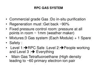
Gas purification process • Gas mixture quality: Presence of impurities in the return gas from the RPCs • Possible worsening of RPC performance due to impurities • Removal of water vapour by combination of 3A and 5A molecular sieves continuous duty purifier. • Removal of oil vapours by 3X molecular sieves • Removal of radicals (F-, HF etc.) by disposable activated Alumina • Removal of Oxygen by CuZn and Ni-NiO on activated Alumina/Silica by continuous duty purifier using standard cartridges • Final goal was to achieve the moisture and Oxygen levels to less than 2 ppm B.Satyanarayana, TIFR, Mumbai XX DAE-BRNS High Energy Physics Symposium, Visva-Bharati January 13-18, 2013
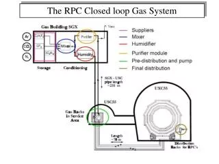
Line diagram of the close loop gas recirculation and purification system PT 2 Displacers Molecular Sieves Molecular Sieves Pneumatic Cylinders Radical Remover Low pressure High pressure Diaphragm Pump PT 1 Gas purifiers Exhaust Receiver tank inlet PT 3 MFC 5 Hygrometer N2 input Non-return valve Bypass Feeder valve Vacuum Pump Storage Tank Outlet PT 6 1 2 3 4 PT 5 RPC stack (this part is outside the gas unit cabinet) Exhaust Mass flow controllers MFC 1,2,3,4 PT 4 • Gas Mixing (On-line) • Gas Recirculation • Gas Purification system • Control System (PLC) MFC 6 Low pressure regulator B.Satyanarayana, TIFR, Mumbai XX DAE-BRNS High Energy Physics Symposium, Visva-Bharati January 13-18, 2013
Some pictures of close loop gas system Rear Front B.Satyanarayana, TIFR, Mumbai XX DAE-BRNS High Energy Physics Symposium, Visva-Bharati January 13-18, 2013
Design parameters of the pilot system • RPCs (12) 8litres x 12 = 96litres +20litres (main cylinder) +20litres (buffer cylinder) • Total Gas in the close loop system ~180litres • If filled at 10/20SCCM will take1000 hours. So high filling rate of say 15litres/min 10Hours is required. • Loop flow = 1litre per minute (80cc/RPC) and top up = 10cc • Positive pressure to be maintained for smooth gas flow through RPCs (1.006 bar to 1.009 bar, i.e. 3mbar difference). • Lab pressure changes between 1.004bar to 1.010bar twice a day. • Auto-refill starts at 1.150bar (set value) • Filled pressure (PT5) is 1.450 bar (set value) • Manual refill after evacuation (Fast refilling) • Provision for exhaust through MFC5 B.Satyanarayana, TIFR, Mumbai XX DAE-BRNS High Energy Physics Symposium, Visva-Bharati January 13-18, 2013
Some resulting numbers • Total gas volume in the system= 101 litres • Main cylinder = 20litres, buffer cylinder = 20litres • Three purifier cylinders = 3x15 = 45litres • Two RPCs = 2x8 = 16Litres • Auto refilling pressure = 1.150bar, auto refill up to = 1.450bar, difference = 0.300bar • Volume of cylinder = 20litres, so gas refilled = 20 x 0.300 = 6litres. • We refill only 6 litres. So, we are filling only about 6 % of the total volume once in 20 days. B.Satyanarayana, TIFR, Mumbai XX DAE-BRNS High Energy Physics Symposium, Visva-Bharati January 13-18, 2013
Performance of close loop system • Depends on maintaining pressure balance, flow rate and efficiency of purification process. • Depends very much on the leak integrity of RPC. • Both factors must be carefully addressed to achieve good efficiency of close loop recirculation. • Operates at very low pressure difference. Typically 10 to 20mmWC. Hence the system is sensitive to changes in the ambient room pressure. • Therefore removed the “High pressure to low pressure regulator” and capillary are connected at the input of RPCs • Removal of Contaminations: Air, Water vapour along with air and break down radicals specially of SF6 B.Satyanarayana, TIFR, Mumbai XX DAE-BRNS High Energy Physics Symposium, Visva-Bharati January 13-18, 2013
Some crucial parts of the system Vacuum- Suction-Compressor PLC – CPU with Display Neoprene - Diaphragm Moisture Sensor + 20mA B.Satyanarayana, TIFR, Mumbai XX DAE-BRNS High Energy Physics Symposium, Visva-Bharati January 13-18, 2013
(High to Low) Pressure regulator Regulates 3bar to 20/300mm WC with adjustable pin/handle on the top of the assembly B.Satyanarayana, TIFR, Mumbai XX DAE-BRNS High Energy Physics Symposium, Visva-Bharati January 13-18, 2013
CLS with a leaky RPC: Refill in 20 hours! AL10 B.Satyanarayana, TIFR, Mumbai XX DAE-BRNS High Energy Physics Symposium, Visva-Bharati January 13-18, 2013
System with 2 RPCs auto-refill in 20 days B.Satyanarayana, TIFR, Mumbai XX DAE-BRNS High Energy Physics Symposium, Visva-Bharati January 13-18, 2013
PT1 after closing CLS’s backdoor Stable phase B.Satyanarayana, TIFR, Mumbai XX DAE-BRNS High Energy Physics Symposium, Visva-Bharati January 13-18, 2013
MFC6 after closing CLS’s backdoor Stable phase B.Satyanarayana, TIFR, Mumbai XX DAE-BRNS High Energy Physics Symposium, Visva-Bharati January 13-18, 2013
AL11: Pressure versus Chamber current Stable phase B.Satyanarayana, TIFR, Mumbai XX DAE-BRNS High Energy Physics Symposium, Visva-Bharati January 13-18, 2013
AL11: Pressure versus noise rates B.Satyanarayana, TIFR, Mumbai XX DAE-BRNS High Energy Physics Symposium, Visva-Bharati January 13-18, 2013
AL15: Pressure versus Chamber current Stable phase B.Satyanarayana, TIFR, Mumbai XX DAE-BRNS High Energy Physics Symposium, Visva-Bharati January 13-18, 2013
AL15: Pressure versus noise rates B.Satyanarayana, TIFR, Mumbai XX DAE-BRNS High Energy Physics Symposium, Visva-Bharati January 13-18, 2013
Residual Gas Analyser (RGA) Setup B.Satyanarayana, TIFR, Mumbai XX DAE-BRNS High Energy Physics Symposium, Visva-Bharati January 13-18, 2013
Typical RGA spectrum B.Satyanarayana, TIFR, Mumbai XX DAE-BRNS High Energy Physics Symposium, Visva-Bharati January 13-18, 2013
Monitoring using Residual Gas Analyser B.Satyanarayana, TIFR, Mumbai XX DAE-BRNS High Energy Physics Symposium, Visva-Bharati January 13-18, 2013
Summary and future outlook • Basic process cycle control is working as per design. • So far 2 RPCs were installed in the close loop system. • All the RPC operating and performance parameters like current and noise rate; ambient parameters such as barometric pressure, temperature and relative humidity; host of closed loop system parameters like RGA, moisture etc. are being monitored round the clock and analysed. • The system is being fine tuned using the results from the monitor data • Found leak rate in the system to be less than 0.01bar • Moisture is found to be less than 2% • More RPCs are being added in the loop • Design of the scaled up version for the ICAL engineering module is in progress B.Satyanarayana, TIFR, Mumbai XX DAE-BRNS High Energy Physics Symposium, Visva-Bharati January 13-18, 2013
B.Satyanarayana, TIFR, Mumbai XX DAE-BRNS High Energy Physics Symposium, Visva-Bharati January 13-18, 2013
Why FLOW Rate ? : velocity distribution (m/s) for 1mX1m RPC , 0.2 Volume changes/day
Case (2) : velocity distribution (m/s) for 1mX1m RPC , 0.5 Volume changes/day B.Satyanarayana, TIFR, Mumbai XX DAE-BRNS High Energy Physics Symposium, Visva-Bharati January 13-18, 2013
Dual :Purifier section B.Satyanarayana, TIFR, Mumbai XX DAE-BRNS High Energy Physics Symposium, Visva-Bharati January 13-18, 2013
Catalysts and Adsorbents • Molecular Sieves: Trap gas molecules of particular size • Sodium, Potassium, Calcium, Aluminum Silicate are used in different proportions to formulate the following sieves: • Type 3A to trap moisture [23% w/w maximum] • Type 4A to trap Argon [Absence of moisture] • Type 5A to trap n-Butane • Type 3X to trap oil vapours • Activated Aluminum to remove radicals such as F-, HF etc. • Catalysts • Activated Alumina + Palladium to promote condensation of IsoButane (Adsorption surface ~200 m2/gm) • Activated Carbon to Adsorb Isobutane • Zirconia based Zeolites (ZSM) to promote Isobutane-n Butane conversions • Silica gel: Wide range of pore size, good for water adsorption (Chemically bonds Water) B.Satyanarayana, TIFR, Mumbai XX DAE-BRNS High Energy Physics Symposium, Visva-Bharati January 13-18, 2013
Leak test by pressure drop scheme • RPC volume (V1): 8000 cc, Pressure (P1): 1020mbar Abs • Reference Pressure (P2): 1000 mbar Abs • Gas content = P1 X V1/P2 = 8160 cc • If 1 cc gas leaks out, effective gas content will be 8160-1 = 8159 cc • After 1 cc leakage RPC pressure will drop to 8159 X 1000/8000 = 1019.875 mbar Pressure drop is 0.175 mbar equivalent to 1.75 mm water column • The target leak rate being 5x10e-4 SCCM , 1 cc leak should take 1/ (5x 10e-4) or 2000 min. (nearly 33 hrs) • The acceptance criteria therefore: “ Pressure drop of less than 1.75 mm WC in more than 33 Hrs.” B.Satyanarayana, TIFR, Mumbai XX DAE-BRNS High Energy Physics Symposium, Visva-Bharati January 13-18, 2013
Transfer and test system for 1m X 1m detector B.Satyanarayana, TIFR, Mumbai XX DAE-BRNS High Energy Physics Symposium, Visva-Bharati January 13-18, 2013
Typical Closed Loop System B.Satyanarayana, TIFR, Mumbai XX DAE-BRNS High Energy Physics Symposium, Visva-Bharati January 13-18, 2013
Basic Components • Moisture sensor, Pan metrics • Oxygen sensor , GE sensing • PLC Siemens • Sequence controller • Completely Automated B.Satyanarayana, TIFR, Mumbai XX DAE-BRNS High Energy Physics Symposium, Visva-Bharati January 13-18, 2013
Partial Pressure • Required Gas concentrations: Say Fr(95%)+Iso(4.5%)+SF6(0.5%) • Evacuate the cylinder (20Ltrs.) to 10-1Torr Pressure after mixing =2 Atmosphere (Abs). PFr +PIso+PSF6=2 Atmp.[10000cnts on display] PSF6=2Atmp X 0.5%=0.01Atmp[50cnts] PIso=2 Atmp X 4.5%=0.09Atmp[450cnts] PFr=2 Atmp X95%=1.9 Atmp[9500Cnts] If 10000 cnts2atmp. Heater ~0.5W gives turbulence to the gas molecules and get mixed properly B.Satyanarayana, TIFR, Mumbai XX DAE-BRNS High Energy Physics Symposium, Visva-Bharati January 13-18, 2013
Features and Functions • Completely automated system using SEIMENS PLC’s • Process control cycle (pumping, flow rate through RPC, topping of gas, regulating valves and sequencing is maintained, bias pressure control etc.) • Lab pressure changes between 1.004 to 1.010bar twice a day. • Typical flow rates are 20SCCM to 100SCCM
MIXING UNIT • This system will have dual supply of mixed gas viz. one for fast fill of the gas in the closed loop system say about 90LPM to fill the gas in loop, which is about 180Liters and the second one with 50 to 100 SCCM (flow need to be understood) to replenish the exhaust gas which will be on-line. This study will tell us the optimum or number of volume changes of gas needed. B.Satyanarayana, TIFR, Mumbai XX DAE-BRNS High Energy Physics Symposium, Visva-Bharati January 13-18, 2013
RGA:Vacuum Analysis Mass spectrometer Stanford Research Systems RS-232c Interface Dual Thoriated-Iridium Filament B.Satyanarayana, TIFR, Mumbai XX DAE-BRNS High Energy Physics Symposium, Visva-Bharati January 13-18, 2013