Download
1 / 42
420 likes | 443 Views
ECE 171 Digital Circuits Chapter 12 Adder. Herbert G. Mayer, PSU Status 4/15/2018 Copied with Permission from prof. Mark Faust @ PSU ECE. Syllabus. Half Adder Half Subtractor Full Adder Ripple Carry Adder Carry Look-Ahead Adder Multiplier Design ALU Design References. Half Adder.

E N D
ECE 171Digital Circuits Chapter 12Adder Herbert G. Mayer, PSU Status 4/15/2018 Copied with Permission from prof. Mark Faust @ PSU ECE
Syllabus Half Adder Half Subtractor Full Adder Ripple Carry Adder Carry Look-Ahead Adder Multiplier Design ALU Design References
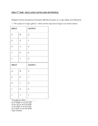
Half Adder A0 B0 CO1 S0 0 0 0 0 0 1 0 1 1 0 0 1 1 1 1 0 A0 + B0 CO1 S0 • Students, now in class: design logic circuit for half 1-bit adder! • Using And- Or, Not- and Xor gates • Using only And- Or- and Not gates
Half Adder A0 B0 CO1 S0 0 0 0 0 0 1 0 1 1 0 0 1 1 1 1 0 A0 + B0 CO1 S0
Half Subtractor A0 B0 BO1 D0 0 0 0 0 0 1 1 1 1 0 0 1 1 1 0 0 A0 + B0 BO1 D0 • Observations about hald adder and half subtractor: • Note that Sum and difference are the same logic, thus circuitry • Only carry & borrow differ in adder vs. subtractor! • So can use adder for subtractor Efficient! • But must build different Borrow: by simply inverting A0 input!
Half Subtractor A0 B0 BO1 D0 0 0 0 0 0 1 1 1 1 0 0 1 1 1 0 0 A0 - B0 BO1 D0
Full Adder: 4 Digits • Consider a circuit to add two 4-bit numbers: A3 A2 A1 A0 + B3 B2 B1 B0 CO4 S3 S2 S1 S0 • Truth table would have 8 inputs (28 = 256 rows) and 5 outputs • Requiring 5 minimized functions (5 8-variable K-maps). • But operation at each bit position (after A0/B0) is identical: COi Ai + Bi COi+1 Si Named:bit slice
Full Adder: Truth Table Students, compute truth table for bit slice of full adder! 1. Inputs are: CI, A, B 2. Output are: CO, S Ignore that first digits do NOT need a carry-in! Pretend carry-in for first digit (digit 0) is always 0
Full Adder: Truth Table CI A B CO S 0 0 0 0 0 0 0 1 0 1 0 1 0 0 1 0 1 1 1 0 1 0 0 0 1 1 0 1 1 0 1 1 0 1 0 1 1 1 1 1 Students, design K-Map for bit slice of full adder: 1. K-Map for carry out CO; inputs A, B, CI 2. K-Map for sum S; inputs A, B, CI
Full Adder: Boolean Expression CI A B CO S 0 0 0 0 0 0 0 1 0 1 0 1 0 0 1 0 1 1 1 0 1 0 0 0 1 1 0 1 1 0 1 1 0 1 0 1 1 1 1 1 Result computed one bit at a time differently: S = CI’ A’ B + CI’ A B’ + CI A’ B’ + CI A B S = CI’ ( A’ B + A B’ ) + CI ( A’ B’ + A B ) S = CI’ ( A xor B ) + CI ( A equiv B ) S = CI xor A xor B q.e.d.
Full Adder: Circuit CI A B CO S 0 0 0 0 0 0 0 1 0 1 0 1 0 0 1 0 1 1 1 0 1 0 0 0 1 1 0 1 1 0 1 1 0 1 0 1 1 1 1 1
Full Adder: K-Map Students, draw circuit for CO and S, from inputs A, B, CI CI A B CO S 0 0 0 0 0 0 0 1 0 1 0 1 0 0 1 0 1 1 1 0 1 0 0 0 1 1 0 1 1 0 1 1 0 1 0 1 1 1 1 1
Ripple Carry Adder A1 A0 + B1 B0 CO2 S1 S0
Ripple Carry Adder • Pros vs. Cons of Ripple Carry Adder: • Identical modules (bit slices) usable • Even lowest digit can use same circuits, by simply grounding carry-in! • No inherent limit on number of digits! • But each digit pair has to wait until all previous sums of digit pairs have been computed • Slow down critical HW module • Must find different method, if speed is of essence!
Modular Two Bit Adder/Subtractor • Single circuit for adder & subtractor • Needs 1 added xor per digitcomputed • And signal: want add or subtract! • Modular to any number of digits to be added, subtracted!
Review of Binary Numbers Binary Digit –AKA Bit-- is the smallest unit of computation on most digital computers Bit has two states: 0 represents 0 Volt [V], or ground; used for logical False, or for numeric 0 1 represents positive Voltage [+V]; used for logical True, or for numeric 1 Computer word consists of multiple bits, typically 32, 60, or 64 bits Often words are composed of bytes, units of 8 bits that are addressable as one unit: byte-addressable General binary number, just like decimal system: LSB MSB bn-1bn-2…b1b0 = bn-12n-1 + bn-22n-2 + … + b121 + b020
Binary Numbers Using TCR Possible representations of binary numbers: sign-magnitude (sm), one’s complement (ocr), and two’s complement representation (tcr) Advantage of tcr: machine needs no subtract unit, the single adder is sufficient as we saw, plus single gate to select add or subtract To create a negative number: invert the positive! See inverter later Also there is no need for signed- and unsigned arithmetic; unsigned is sufficient C and C++ allow signed & unsigned integers. In fact, arithmetic units using tcr can ignore the sign bit Tcr just needs an adder and minor additional circuitry to cover both
Binary Numbers Using TCR Binary numbers in tcr use a sign bit and a fixed number of bits for the magnitude For example, on an old PC you may have 32-bit integers, 1 for the sign, 31 for the magnitude Or more typical today your PC may have 64-bit integers With 64-bit integers, 1 for the sign, 63 for the magnitude When processed in a tcr architecture, the most significant bit is the sign bit, the other 31 (or 63) bits hold the actual signed value of interest By convention, a sign bit value of 0 stands for positive and 1 for negative numbers
Binary Numbers Using TCR Inverter +: To create a negative number from a positive in tcr, start with the binary representation for the positive one, invert all bits, and add 1 Note that overflow cannot happen by inversion alone: the inverse (negative value) of representable, positive numbers can always be created There is one more negative number than positive ones in tcr There is one single 0, i.e. no negative 0 in tcr, as in one’s complementand sign-magnituderepresentations
Binary Numbers Using TCR Inverter -: To invert negative number in tcr, complement all bits of the original negative number and add a 1 Ditto with inverting a negative to a positive number: It is important to add a 1 again, not to subtract it! However, there will be one negative value, whose positive inverse cannot be represented; it will cause overflow instead! That value is the smallest, negative number. For example, an 8-bit signed tcr integer can hold integers in the range from -128 .. 127. See the asymmetry? See the one negative value that cannot be inverted? On a 32-bit architecture, the range is from -2,147,483,648 to +2,147,483,647. See the asymmetry?
Propagation Delay in Ripple Adder Assuming S is implemented using AND, OR, XOR, NOT S: Tpd = 3 tp CO: Tpd = 2 tp
Partition Carry-Out Logic Settling time for n stage ripple adder ST = 3tp + (n-1)(2tp) = (2n+1)tp S of MSB stage C of remaining earlier n-1 stages
Using HA for LSB Stage If we use HA for 1st stage (no CI) ST = 3tp + (n-2)(2tp) + tp = (2n)tp
Carry Look-Ahead Adder Con+1 logic not dependent upon entire prior stage (COn) logic
Carry Look-Ahead Adder G (carry generate) is dependent upon current stage's ability to generate a carry. P(carry propagate) is dependent upon current (and prior) stages ability to propagate a carry. A carry is generated at a stage i if it is generated by stage i’s inputs (Ai,Bi) or by any prior stage and propagated by every succeeding stage.
Carry Look-Ahead Adder Con+1 logic not dependent upon entire prior stage (COn) logic Uses: G0 through Gn-1 and P1 through Pn-1 Settling Time = 6tp (constant) for 3 or more stages
Speed Improvement Ripple Carry Adder (n) Stages using HA for LSB (2n)Tp Carry Look-Ahead Adder (n) Stages (using SOP) 6Tp Speed up for n stage adder ((2n)Tp-6Tp)/(2nTp) Assume 4 stages (2 x 4 – 6)/(2 x 4) 2/8 25%
Speed Improvement Ripple Carry Adder (n) Stages using HA for LSB (2n)Tp Carry Look-Ahead Adder (n) Stages (using SOP) 5Tp Speed up for n stage adder ((2n)Tp-5Tp)/(2n)Tp) Assume 4 stages (2 x 4 – 5)/(2 x 4) 3/8 37.5%
Limits to Speed Up • Carry generation G0 of first stage must be capable of driving all succeeding stages • Each succeeding stage requires gates with increasing number of inputs (fan-in) • Gate count increases with each stage
Expandable Carry Look-Ahead Adder 74LS83A & 74LS283
Carry-Save Adders(Wallace Tree Summing Network) Adding more than two operands with full adders (A,B,CI,CO) A0 B0 + C0 S10 CO11 + D0 S21 S20 CO21 + E0 S31 S30 CO32 CO31 + CO42_________ S42 S41 S40