Download
1 / 21
210 likes | 215 Views
E-learning Module 1 Scanning at 7T. Introduction. This module introduces main elements that differentiates scanning at 7T from scanning at 3T, from a users perspective.

E N D
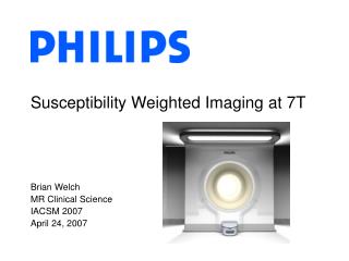
E-learning Module 1 Scanning at 7T
Introduction This module introduces main elements that differentiates scanning at 7T from scanning at 3T, from a users perspective. Aspects of 7T physics are described, and examples of how that impact scanning will be given, with a focus on the additional challenges of scanning at 7T. In the end is a small quiz that can be used for testing your understanding.
Effects of going from 3T to 7T M0 T1 T2 Susceptibility sensitivity Chemical shift B1 effects Spin polarization is increased, which often is exploited to increase resolution and makes it more feasible to do imaging with other nuclei than protons 3T 13 mm3 (3D T1w TFE) Relaxation times are altered which benefits some sequences, challenges other This gives new contrast possibilities and is a benefit for fMRI, but comes with challenges that makes B0 shimming essential This gives increased spectral resolution in MRS, allowing identification of otherwise ‘hidden’ metabolites. A challenge is the water/fat displacement errors. The increased larmor frequency leads to many challenges at 7T, such as increased SAR and B1 inhomogenieties, but also makes it possible to increase scan time acceleration with SENSE 7T 0.63 mm3 (3D T1w TFE)
M0 Spin polarization increases with field strength, and ignoring relaxation times: Thus MR techniques with low sensitivity, such as MR spectroscopy and experiments with other nuclei than protons are therefore more attractive at 7T. • SNR is often exploited to increase resolution, making it possible to see smaller structures. • SNR voxel volume, so resolution increase achievable when going from 3T → 7T for constant SNR (rules of thumb): • voxel size can be decreased by with isotropic voxels (this means 1mmiso @ 3T → 0.75mmiso @ 7T) • voxel size can be decreased by n plane, when keeping the slice thickness (in-plane 1mm @3T →0.65mm @7T)
Relaxation time changes Because of the changes in relaxation times, sequence design needs to be re-considered at 7T The altered relaxation times benefit some sequences, and challenges other For many structural sequences, the increase in T1 require longer TRs to exploit the SNR gain of 7T For arterial spin labeling (ASL) and time of flight (TOF) angiography, the longer T1 is an advantage, as it gives improved suppression of stationary tissue TOF @ 7T
Susceptibility sensitivity Materials are magnetized according to their magnetic susceptibility, thereby altering the background field. The field variations in the subject due to the susceptibility variations increases with field strength. Consequences of going from 3T to 7T are therefore • B0 inhomogeneities • T2* This can lead to increased geometric distortions, signal dropout, poor fat suppresion. To compensate the B0 inhomogeneities, higher order B0 shimming is often performed at 7T.
B0 shimming For brainimaging, most often image based shimming is used. This is done by acquiring a B0 map as a separate scan. The shim tool performs brain extraction and estimates the best shim, using only the voxels inside the brain mask In subsequent scans, the estimated shimming parameters are used
Susceptibilitysensitivity The increased sensitivity to magnetic susceptibility differences at 7T is also one of the main benefits as it improves contrast in sequences based on susceptibility contrast, e.g.: SWI Gradient echo fMRI at 7T
B1 effects - SAR When going to higher field the Larmor frequency increases (128 MHz @3T → 298 MHz@7T.) This has the direct consequence, that the specific absorption rate (SAR) goes up More often than at 3T, sequence design is therefore limited by SAR Ways to lower SAR in a sequence includes • Increasing TR; • lowering max B1 allowed (this will stretch the pulses in time to preserve flip angles)
B1 effects – spatial B1 field The RF wavelength in tissuedecreases with increasing RF frequency, and tissueconductivityincreases. At 7T the RF wavelength in tissue is ~13cm, and constructive/destructiveinterferencesbetweenfields from differentcoil elements and/or reflectedfieldscanthereforeoccurinside the human head. This leads to more inhomogenous B1 fields, than at lowerfieldstrengths => Large variations in flip angles accross the field of view The effect is particularlypronounced for spin-echosequences % of nominal B1 127 67 B1 map in a head @7T (sagittal view) T2w GRASE T2w GRASE
B1 effects – spatial B1 field Because of the destructive interferences and SAR limits, there is no RF body coil built in to thethe bore of the 7T Philips Achieva scanner. Instead local RF transmit coils are used. To reduce/control the transmit B1 inhomogeneitiesseveralstrategiesareusedincluding 2 chTx/Rx head coil • AdiabaticRF pulses • Dielectricpadsplacedstrategically in the coil • Multiple transmitcoil elements whichwaveformscanbecontrolledindividually (multitransmit) Knee coil, 1ch Tx, 28ch Rx Dielectric pads 32ch Rx head coil
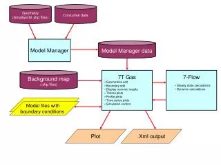
Multitransmit Multitransmit holds great promise to control B1-inhomogenieties, though exploiting it optimally is still a large research area The Philips Achieva scanner in Lund can be run with either the ‘classic’ or ‘Mtx8’ system ‘Classic’ is a 2 channel RF transmit system, while ‘Mtx8’ is an 8 channel RF transmit system Each system has separate RF amplifiers, RF coils and scanner computers (host, acquisition computer and reconstructor) Which system to use is controlled by a switch The user interfaces of the two systems are very similar. MTx8 host Classic host
B1 effects – spatialreceivesensitivities The shortened RF wavelength and increased conductivity at 7T also has a benefit: The coil sensitivities become more structured and distinct. This, combined with the increased SNR, favors going to higher SENSE factors than at lower field strengths. SENSE principle Coil sensitivities Undersampled images Coil ch. 1 Unfolded image Coil ch. 2 => & Coil ch. 3 Coil ch. 4
Chemical shift The chemical shift is increased at 7T compared to 3T This benefits MR spectroscopy (MRS), as spectral resolution increases, allowing identification of otherwise hidden metabolites. Extra features for MRS are in the 7T Philips Achieva software, that are not in the 3T software, including: • A second basing pulse • In-base water reference acquisition for B0 phase correction • Volume selective RF power optimization See the instructions for use for details
Quiz question 1 - Answers At 7T spin polarization is increased compared to 3T, which means an increase in SNR. This can be exploited to increase resolution. The following rule of thumb applies (ignoring relaxation) for increasing the resolution @7T compared to 3T for constant SNR: • voxel size can be decreased by 2.33 in all directions (this means 1mmiso @ 3T → 0.42mmiso @ 7T) • Voxel size can be decreased by 2.33 in one direction (this means slice thickness of 1mm @ 3T → slice thickness of 0.42mm @ 7T) • Voxel size can be decreased by n both in-plane directions, when keeping the slice thickness (in-plane 1mm @3T → 0.65mm @7T) • Voxel size can be decreased by in all directions (this means 1mmiso @ 3T → 0.75mmiso @ 7T) Click for answers Click for next question
Quiz question 2 - Answers The following is true about the relaxation times of most tissues and chemical shift effects when going from 3T to 7T: • T1↑, T2↓ , T2*↓, chemical shift ↑ • T1↓, T2↓ , T2*↓, chemical shift ↑ • T1↓, T2 ↑, T2* ↑, chemical shift↓ • The change in T1 is a benefit for time of flightangiography and the change in chemicalshift is a benefit for spectroscopy • The change in T1 typicallyleads to shorter scan durations Click for answers Click for next question
Quiz question 3 - Answers Strategies to control these artefacts, include • Increasing SENSE factor • B0 shimming • Dielectric pads placed strategically • Multitransmit 8 Click for answers Click for next question
Quiz question 4 - Answers The following is true about the hardware at the 7T Philips Achieva in Lund. • The RF body coil built in to the bore of the scanner is longer than at 3T • ‘Mtx8’ and ‘classic’ are two different systems that the scanner can be runned with. Each system has separate RF amplifiers, RF coils and scanner computers (host, acquisition computer and reconstructor) • ‘classic’ has one RF channel for transmit. • The 1H-RF coils of the scanner are tuned to 128 MHz. Click for answers - There is no RF body coil built in to the bore of the 7T scanner - Classic is a dual transmit system -The 1H RF coils are tuned to 298 MHz which is the Larmor frequency at 7T. Click for next question
Quiz question 5 - Answers The following is true about about scanning at 7T. • Artefacts caused by poor B0 shimming are exclusively geometric distortions and signal dropout. • For brain imaging, B0 shimming is typically performed for echo-planar imaging and spectroscopy sequences only • Gradient echo fMRI benefits from the increased SNR, susceptibility sensitivity and high SENSE factors feasible at 7T Click for answers - Poor B0 shimming can also lead to poor fat suppression which can be more difficult to realize. So if encountering an artefact at 7T, very often poor B0 shimming is the culprit. - Because of the severe B0 inhomogenieties, B0 shimming is typically performed for almost all sequences. - The increased SNR is often used for higher resolution, the susceptibility sensitivity gives impressive contrast and the high achievably SENSE factors are beneficial for reducing distortions and minimizing TR. Click to finish