Download
1 / 11
110 likes | 320 Views
An Adder. A Subtractor. Arithmetic Logic Unit. A and B are the inputs of the adder/ subtractor R is the output of the adder/ subtractor F is the control to tell it to add or subtract D is the status to tell us when it is done (or maybe something else?). A Flip Flop. A 4 bit register.

E N D
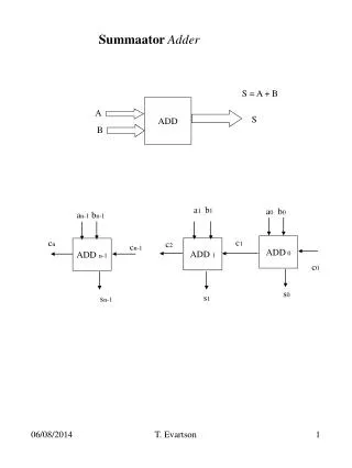
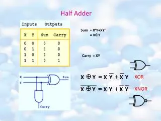
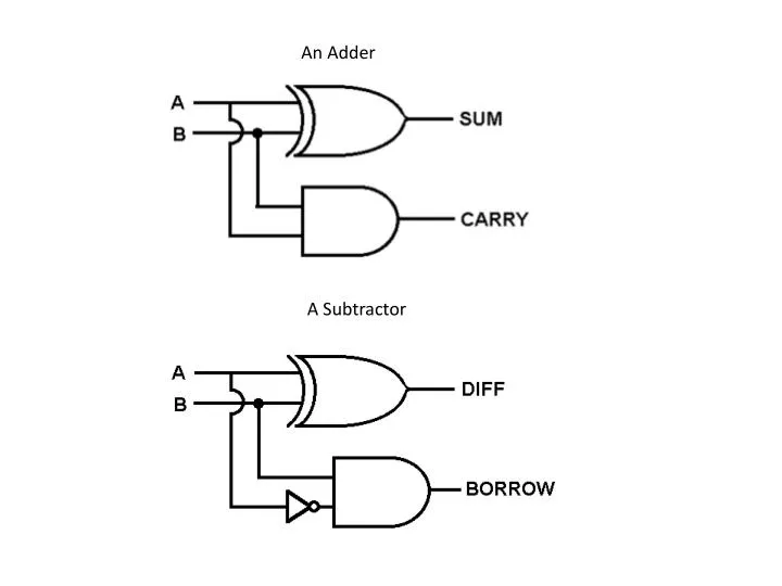
An Adder A Subtractor
Arithmetic Logic Unit A and B are the inputs of the adder/ subtractor R is the output of the adder/ subtractor F is the control to tell it to add or subtract D is the status to tell us when it is done (or maybe something else?)
A Flip Flop A 4 bit register
Decoder Add Subtract AND OR To ALU Add Subtract AND OR
Von Neumann Architecture Harvard Architecture
Atmel Registers Note: R0 to R15 will not work with some instructions
Status Register I – Global Interrupt enable flag, must be set for interrupts to work T – Bit copy storage, used with BST and BLD H – Half carry flag, detects carry from lower nibble S – Sign flag, exclusive OR between N flag and V flag V – Two’s complement overflow flag N – Negative flag, result of an operation is negative Z – zero flag, result of an operation is zero C – Carry flag, indicates an overflow after count reaches 255