Download
1 / 14
150 likes | 724 Views
Semi-Hermetic Compressors for CO 2 Cascade Systems. Hermann Renz Bitzer Kuehlmaschinenbau GmbH Germany. Semi-Hermetic Compressors for CO 2 Cascade Systems. Contents Introduction Example of CO 2 cascade system Properties of CO 2 vs. R22 Requirements on compressor design

E N D
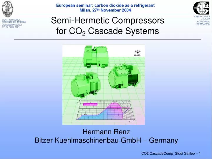
Semi-Hermetic Compressorsfor CO2 Cascade Systems Hermann Renz Bitzer Kuehlmaschinenbau GmbH Germany
Semi-Hermetic Compressorsfor CO2 Cascade Systems Contents • Introduction • Example of CO2 cascade system • Properties of CO2 vs. R22 • Requirements on compressor design • Development Stages / Design Features • Summary
Introduction Due to its environmentally benign characteristics and specific properties CO2 has good potential for: • The extended use in subcritical cascade systems like for example: • Supermarket applications • Industrial refrigeration systems • Specific features • Very high volumetric cooling capacity • Favourable TEWI, energy demand & installed cost • Reasonable safety requirements
Example of Supermarket Application – MT with HFC / LT with CO2Cascade
Comparison of Properties –Low Temp CO2 Cascade vs. R22 Compressor displacement counter-proportional to relative cooling capacities
Requirements on Compressor Design • Consideration of CO2 properties • High Pressure levels • Strength of housing and crank gear • High volumetric cooling capacity • Adaptation of displacement relative to motor power • High vapour density / absolute mass flow • Adaptation of working valves & cross sections • High gas solubility in oil • General requirements • High isentropic efficiency • Compact & solid design, use of “standard” parts
Design Features Pressure Levels • High pressure levels of CO2 • Compressor housing with high strength pressure • Safety factor “3“ acc. (pr)EN12693 • Required pressures (approx.) • HP 40 bar • LP 25 bar (standstill pressure) • Realised compressor construction • Compact design • Closed housing w/o bottom plate
Design FeaturesDisplacement / Crank Gear(1) • Adaptation of displacement • Optimum match to “standard” motor sizes • Potential for the use of “standard” parts • cost issue • Smaller displacement allowing for generously sized crank gear
Design FeaturesDisplacement / Crank Gear(2) • Adaptation of displacement by modified piston stroke • Allowing for larger piston diameter • Potential for generously sized piston pin • and for special piston pin bearing • Connecting rods with closed big end (large diameter) • Potential for large cross sections of working valves • Adaptation to high vapour density • Improvement of compression process • Reduced piston velocity • Improved running smoothness
Lubricant Issues with CO2 Compressors Relevant to compressor • Heavy mechanical load on crank gear • High gas solubility in oil • Strong oil foaming tendency with pressure fluctuations • High danger of boundary friction Relevant to (commercial) refrigerating systems • Oil return from system / avoiding strong oil migration and fouling effects in heat exchangers require: • Good flow characteristics, low viscosity on suction side • Sufficient miscibility with CO2 Suitable Solution especially formulated POE lubricant
kin. viscosity [mm2/s] VapourPressure [bar] Temperature [°C] Concentration [M-% Oil in CO2] Oil / Refrigerant (CO2) Properties Phase separation Temperature [°C]
Compressor Lubrication • Enhanced centrifugal lubrication • Quick oil supply after start • Enlarged oil pocket atthe shaft end • Separation of oil foam by gravity principle • Reduced oil carry over • minimum oil side flow • Potential for oil monitoring system in oil pocket
Summary • Convincing arguments for the application of CO2 in low temperature cascade systems • Very high volumetric cooling capacity – allowing for: • Small compressor displacement • Small pipe sizes, favourable installed cost • High specific load on compressor housing and crank gear to be considered • High pressure levels & vapour density • Need for • Adapting compressor design and • Lubrication system