Download
1 / 8
80 likes | 164 Views
Press Brakes, NC Press Brake, NC Press Brake Manufacturers, CNC Press Brake Manufacturers<br><br><br>For more details please visit us at: http://www.energymission.com<br><br>

E N D
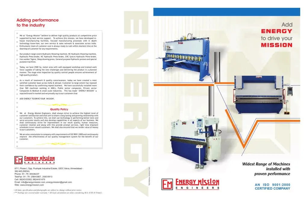
Adding performance to the industry We at “Energy Mission” believe to deliver high quality products at competitive price supported by best service support. To achieve this mission, we have developed in- house manufacturing facilities, focused manufacturing processes with in depth technology know-how, our own service & sales network & associates across India. Enthusiastic team of customer care is always ready to rush within shortest time at the doorstep of customer for any requirements. Our product range covers Hydraulic Shearing machine, NC Hydraulic Shearing machine, Hydraulic Press-brake, NC Hydraulic Press-brake, CNC Syncro Hydraulic Press-brake, Iron worker 'Sigma', Deep drawing press, General purpose Hydraulic presses and special purpose machines. Today, we have 2500 Sq. meter area with well-equipped workshop and trained work force capable of taking the new challenges and delivering the product in a planned manner. The stage wise inspection by quality control people ensures achievement of high quality product. As a result of teamwork & quality consciousness, today we have created a most satisfied customer base across India & abroad. Customer to large extent has reposed their confidence by confirming repeat business. We have successfully installed more than 500 machines working in MNCs, Public sector companies, Private sector Companies & Medium & small scale industries. This has made ' ENERGY MISSION ' a reputed brand in market and we proudly say to our customers that ADD 'ENERGY' TO DRIVE YOUR 'MISSION'. Quality Policy We at Energy Mission Engineers, shall always strive to achieve the highest level of customer satisfaction and shall aim to share a long lasting and growing relationship with our customers. To achieve this, we shall use technology in performing better tests and serve accurate results and also develop capabilities in all aspects of our business. We shall continuously strive for improvement in our result quality, human resources, customer relation and along with this provide prompt services, right time shipment schedules to our valued customers. We shall also ensured that we render value of money to our customers. We are also commutate to company with requirements of ISO 9001:2000 and continuously improve the effectiveness of our quality management system for the benefit of our customer. Widest Range of Machines TECHNOfirm 9426407393 87/1, Phase I, Opp. Pushpak Industrial Estate, GIDC Vatva, Ahmedabad - installed with 382 445 (INDIA) Phone : 91 - 79 - 65436237 proven performance TeleFax : 91 - 79 - 2584 0067, 2583 0913 Cell : 98243 03302, 98244 81470 Email : info@energymission.com, energymission@gmail.com Web : www.energymission.com AN ISO 9001:2000 CERTIFIED COMPANY • All data, specification and photographs are subject to change without prior notice. 2 • ** Toolings not covered under warranty. • All load calculations are done considering M.S. (UTS 45 N/mm ).
Silent Features ! Better cutting accuracy in thin sheets at lower rake angle ! Higher cutting capacity at max. rake angle HYDRAULIC SHEARING MACHINE ! Less power consumption ! Better safety for operator and machine ! Fast production on smaller jobs ! NC upgradation possible ! Low noise & smooth operation gives higher efficiency of operator Variable Rake Angle Adjustment for higher thickness cutting than nominal capacity. Also thin sheets can be cut at lower rake angle ensures twist free cut. Rake Angle can be easily adjusted through selector switch. The stable, robust, ultrasonically ] tested IS 2062 welded steel plates structure as per guidelines of IMTMA standards. ] Ram & Table designed with inclined member & box type structure for maximum strength. ] Positive holding of avoids slippage of sheet during cutting Hyd. Hold downs stroke. ] HCHCr Blade suitable to MS & SS. ] Hardened Transfer bars. ] Optional Ball Transfer Table for fast and ] Front gauging by disappearing stoppers smooth handling of material. mounted on front squaring arm. ] Degree Protector Arrangement for taper cutting of sheets. ] . Specially designed International quality hydraulics components compact manifolds gives smooth, silent & jerk less operation. International quality ensure trouble free electrical components operation over a period of time. RANGE : 3 mm to 25 mm The fastest & easiest setting for burr free Pre calibrated LENGTH : 1250 mm to 7000 mm blade clearance ] Robust, heavy & accurate back gauge cutting. with various drive options.
Nominal Rake Packing Cutting Rake Angle Holding Shearing Capacity Rake ANgle Power Dimension No. of Length Stroke per min Force Angel range (LXWxH) Hold Model downs Thickness in mm in in mm in degree Min. Max. in Kg. in HP in mm NC HYDRAULIC SHEARING MACHINE degree M.S. S.S HVR 320 2000 3.15 4 2 3.15 1°15' 0.5-3° 20 11 11 2000 3 2700x1250x1950 HVR 325 2500 3.15 4 2 3.15 1°15' 0.5-3° 25 13 13 2300 5 3200x1250x2000 HVR 330 3000 3.15 4 2 3.15 1°15' 0.5-3° 21 9 16 2600 5 3700x1400x2100 HVR 340 4000 3.15 4 2 3.15 1°15' 0.5-3° 12 6 20 3200 7.5 4700x1500x2250 HVR 415 1500 4 6 3 4 1°37' 0.5-3° 25 13 8 4500 7.5 2250x1250x2050 HVR 420 2000 4 6 3 4 1°37' 0.5-3° 23 11 11 6200 7.5 2750x1250x2100 HVR 425 2500 4 6 3 4 1°37' 0.5-3° 21 8 13 8000 7.5 3300x1400x2250 Silent Features HVR 430 3000 4 6 3 4 1°37' 0.5-3° 21 10 16 10000 10 3700x1500x2400 HVR 440 4000 4 6 3 4 1°37' 0.5-3° 15 6 20 12000 10 4700x1650x2600 ! NC controller from Delem HVR 450 5000 4 6 3 4 1°37' 0.5-3° 10 3 24 15000 10 5700x1700x2750 HVR 460 6000 4 6 3 4 1°37' 0.5-3° 10 3 28 15000 10 6700x1800x2850 ! 99 steps automatic back HVR 615 1500 6 8 4 6 1°45' 0.5-3° 22 8 8 6500 10 2250x1300x2100 HVR 620 2000 6 8 4 6 1°45' 0.5-3° 20 7 11 6500 10 2750x1350x2150 gauge program HVR 625 2500 6 8 4 6 1°45' 0.5-3° 24 8 13 8500 15 3300x1500x2300 HVR 630 3000 6 8 4 6 1°45' 0.5-3° 22 6 16 10800 15 3800x1650x2500 ! Hardened & ground ball screw HVR 640 4000 6 8 4 6 1°45' 0.5-3° 22 6 20 13600 20 4800x1700x2750 HVR 650 5000 6 8 4 6 1°45' 0.5-3° 18 4 24 16500 20 5700x1800x2850 with linear motion bearing HVR 660 6000 6 8 4 6 1°45' 0.5-3° 14 3 28 19500 20 6700x1900x2950 HVR 815 1500 8 10 6 8 2° 0.5-3° 15 8 8 10500 10 2250x1350x2100 ! Stroke counting on screen HVR 820 2000 8 10 6 8 2° 0.5-3° 18 8 11 12000 15 2750x1450x2250 HVR 825 2500 8 10 6 8 2° 0.5-3° 20 8 13 16500 20 3300x1650x2450 ! Rake angle control thru HVR 830 3000 8 10 6 8 2° 0.5-3° 18 6 16 18500 20 3800x1800x2600 HVR 840 4000 8 10 6 8 2° 0.5-3° 16 4 20 23000 20 4800x1850x2800 selector switch HVR 850 5000 8 10 6 8 2° 0.5-3° 12 3 24 27000 25 5750x1950x2900 HVR 860 6000 8 10 6 8 2° 0.5-3° 8 2 28 31000 25 6750x2100x3100 HVR 1015 1500 10 13 8 10 2° 0.5-3° 14 6 8 10500 10 2250x1350x2200 HVR 1020 2000 10 13 8 10 2° 0.5-3° 18 8 11 13000 15 2750x1500x2300 HVR 1025 2500 10 13 8 10 2° 0.5-3° 15 8 13 17500 20 3300x1650x2500 HVR 1030 3000 10 13 8 10 2° 0.5-3° 12 6 16 20000 20 3800x1850x2750 HVR 1040 4000 10 13 8 10 2° 0.5-3° 13 6 20 25000 25 4800x1950x2850 HVR 1050 5000 10 13 8 10 2° 0.5-3° 10 5 24 30000 30 5750x2050x3000 HVR 1060 6000 10 13 8 10 2° 0.5-3° 8 3 28 35000 30 6750x2200x3300 HVR 1320 2000 13 16 10 13 2° 1-3° 15 8 11 16000 25 2850x1800x2600 HVR 1325 2500 13 16 10 13 2° 1-3° 13 6 13 20000 25 3350x1900x2750 HVR 1330 3000 13 16 10 13 2° 1-3° 11 6 16 25000 25 3800x1950x2850 HVR 1340 4000 13 16 10 13 2° 1-3° 9 4 20 30000 30 4800x2000x2950 HVR 1350 5000 13 16 10 13 2° 1-3° 9 4 24 35000 40 5750x2150x3150 HVR 1360 6000 13 16 10 13 2° 1-3° 7 3 28 40000 40 6750x2300x3500 HVR 1620 2000 16 20 13 16 2° 1-3° 18 6 11 20000 30 3000x1900x2800 HVR 1625 2500 16 20 13 16 2° 1-3° 15 5 13 25000 30 3500x2000x2900 HVR 1630 3000 16 20 13 16 2° 1-3° 12 5 16 28000 30 4000x2000x3000 HVR 1640 4000 16 20 13 16 2° 1-3° 7 3 20 33000 30 4800x2050x3100 HVR 1650 5000 16 20 13 16 2° 1-3° 7 3 24 38000 40 5750x2250x3300 HVR 1660 6000 16 20 13 16 2° 1-3° 5 2 28 43000 40 6750x2350x3700 HVR 2025 2500 20 25 16 20 2° 1-3° 12 5 13 28000 40 3500x2000x3000 HVR 2030 3000 20 25 16 20 2° 1-3° 11 5 16 35000 40 4000x2100x3200 HVR 2040 4000 20 25 16 20 2° 1-3° 9 4 20 40000 50 4800x2200x3300 NC Value Addition : HVR 2050 5000 20 25 16 20 2° 1-3° 8 3 24 45000 60 5800x2350x3500 HVR 2060 6000 20 25 16 20 2° 1-3° 5 2 28 50000 60 6800x2450x4100 HVR 2525 2500 25 30 20 24 2° 1-3° 10 4 13 36000 60 3400x2250x3300 HVR 2530 3000 25 30 20 24 2° 1-3° 8 4 16 45000 60 4000x2300x3300 HVR 2540 4000 25 30 20 24 2° 1-3° 7 4 20 50000 75 5000x2300x3500 HVR 2550 5000 25 30 20 24 2° 1-3° 5 2 24 55000 75 6000x2450x3700 HVR 2560 6000 25 30 20 24 2° 1-3° 3 1 28 60000 75 7000x2600x4300 STANDARD ACCESSORIES (NC CONTROL) STANDARD ACCESSORIES OPTIONAL ACCESSORIES ! Main Drive Motor. ! HMI with 2 Line 16 character LCD monochrome screen & ! Motorized back gauge with DRO. ! Electric Control Panel. numeric keypad. ! Second squaring arm on other side. ! Operational Consol. ! Main Drive Motor. ! Front support with roller according to ! Rake angle selection through selector switch ! Electric Control Panel. required length. ! Lever operated Blade clearance with calibration. ! Hardened Ground Ball screw & Linear motion bearings . ! Rear Sheet support. ! Fine stroke adjustment rod with limit switch ! Two-speed AC motor for back gauge drive. ! Timer belt drive for back gauge. ! Front sheet support. ! Rake angle selection through selector switch. ! Ball Transfer Table. ! Squaring arm with steel rule. ! Lever operated Blade clearance with calibration. ! Degree protector for angular cutting. ! Hardened Transfer bars mounted on table ! Stroke adjustment through screen. ! Stroke counter. ] HMI with 2 Line 16 character LCD monochrome screen & numeric ] Hardened ground Ball screw with better position accuracy ! Hold down cylinders. ! Front sheet support. ! Design with throat depth. keypad. ] Linear motion bearings for smooth & accurate guiding. ! Cutting area illuminated for clear view of blades. ! Squaring arm with steel rule. ! First fill of Hydraulic oil. ] 99 steps back gauge position program ] Various drives interface like two-speed motor, stepper motor or AC ] Stroke control on screen servo motor ! Four edge HCHCr Blade suitable to MS & SS. ! Hardened Transfer bars mounted on table. ] Stroke counter on screen ] Optional Timer belt drive ! Manual Back Gauge. ! Hold down cylinders. ] Rake angle adjustment through selector switch ! Cutting area illuminated for clear view of blades. ! Four edge HCHCr Blade suitable to MS & SS.
Silent Features ! Compact cylinders & low pressure system due to rear cylinder design ! Better rigidity & load carrying capacity against fatigue failure HYDRAULIC PRESS BRAKE ! Positive synchronisation of cylinders with welded torque tube ! Better safety for operator & machine ! Low power consumption ! Three speed system for higher productivity ! Fast production on smaller jobs ! NC upgradation possible ! Low noise & smooth operation gives higher efficiency of operator International quality ensure trouble free electrical components operation over a period of time. International quality . Specially designed hydraulics components compact manifolds gives smooth, silent & jerk less operation. ] low & high pressure and hard Hydraulic cylinder with twin type sealing chrome plated rod with special type guide for long life without leakage. ] Centralized lubrication with flow control ensures adequate lubrication at all points. Front operated manual back gauge with micro-adjustment. Moving work station with ON/OFF controls, Emergency push button & selector for Manual, Semi-Auto & Automatic mode for easy operation & safety. ] The stable robust welded steel frame made of ultrasonically tested IS 262 plates as per guidelines of IMTMA standards. ] Fast approach & fast return speeds to save cycle time, slow pressing speed for better stroke control & bending accuracy, ensures high productivity. ] Repetitive accuracy within ± 0.04 mm. ] Accurate & fine Ram Position Control by micro limit switch. RANGE : 20 MT to 600 MT ] Five piece adjustable guides with special wear resistant liners. LENGTH : 1250 mm to 7000 mm Ram tilting arrangement to maintain bending accuracy over a period.
Return speed Throat Depth Open Height TableLength Ram Stroke Table Width Dimensions Clear Pass Approach Tonnage Capacity Pressing Bending Packing Power Model NC HYDRAULIC PRESS BRAKE in MT in mm in mm in mm in mm in mm in mm in mm in mm HP (LxWxH) PBR 215 20 1500 1.6x1500 2x1250 125 1050 100 250 100 35-9-35 3 1700x1050x1900 PBR 320 30 2000 2x2000 3x1250 125 1550 100 250 200 30-7-40 3 2200x1150x1900 PBR 420 40 2000 2.5x2000 3x1500 180 1550 100 250 200 40-6-45 5 2200x1150x1800 PBR 425 40 2500 2x2500 3x1500 180 2050 100 250 200 40-6-45 5 2700x1150x1900 PBR 430 40 3000 1.6x3000 3x1500 180 2550 100 250 200 40-6-45 5 3200x150x2000 Silent Features : PBR 515 50 1500 4x1500 5x1250 180 1050 100 250 200 35-6-40 5 1700x1150x1900 ! Suitable for complex job bending PBR 520 50 2000 3x2000 4x1500 180 1550 100 250 200 35-6-40 5 2200x1150x1900 PBR 525 50 2500 2.5x2500 3x2000 180 2050 100 250 200 35-6-40 5 2700x1150x1900 ! Ram axis Y and back gauge axis X can be PBR 530 50 3000 2x3000 2.5x2500 180 2550 100 250 200 35-6-40 5 3200x1150x2000 controlled PBR 540 50 4000 1.6x4000 2x3000 180 3100 100 250 200 35-6-40 5 4200x1250x2300 PBR 625 65 2500 3x2500 4x2000 180 2050 150 330 200 35-5-40 5 2700x1200x2000 ! Bend angle & Depth mode programs PBR 630 65 3000 2.5x3000 3x2500 180 2550 150 330 200 35-5-40 5 3200x1200x2000 PBR 640 65 4000 2x4000 2.5x3000 180 3100 150 330 200 35-5-40 5 4200x1250x2400 ! Highly precise Magnetic type press brake scale PBR 820 80 2000 5x2000 6x1500 180 5100 150 330 200 40-6-45 7.5 2200x1550x2100 ! Hardened & ground ball screw with linear PBR 825 80 2500 4x2500 5x2000 180 2050 150 330 200 40-6-45 7.5 2700x1550x2300 PBR 830 80 3000 3x3000 4x2500 180 2550 150 330 200 40-6-45 7.5 3250x1550x2300 motion bearings PBR 840 80 4000 2.5x4000 3x3000 180 3100 150 330 200 40-6-45 7.5 4250x1650x2500 PBR 850 80 5000 2x5000 2.5x4000 180 4100 150 330 200 40-6-45 7.5 5300x1650x2700 ! 128 x 16 bend program memory PBR 860 80 6000 1.6x6000 2x5000 180 5100 150 330 200 40-6-45 7.5 6300x1750x2800 ! Automatic degree & back gauge position as per PBR 1025 100 2500 5x2500 6x2000 180 2050 150 330 200 43-6-48 10 2700x1550x2300 PBR 1030 100 3000 4x3000 5x2500 180 2550 150 330 200 43-6-48 10 3250x1550x2300 program PBR 1040 100 4000 3x4000 4x3000 180 3100 150 330 200 43-6-48 10 4250x1650x2500 PBR 1050 100 5000 2.5x5000 3x4000 180 4100 150 330 200 43-6-48 10 5300x1700x2800 PBR 1060 100 6000 2x6000 2.5x5000 180 5100 150 330 200 43-6-48 10 6300x1750x2900 PBR 1225 125 2500 6x2500 8x2000 230 2050 150 350 300 40-6-50 15 2750x1650x2700 PBR 1230 125 3000 5x3000 6x2500 230 2550 150 350 300 40-6-50 15 3250x1650x2500 PBR 1240 125 4000 4x3500 5x3000 230 3100 150 350 300 40-6-50 15 4250x1650x2600 PBR 1250 125 5000 3x5000 4x4000 230 4100 150 350 300 40-6-50 15 5300x1750x2900 PBR 1260 125 6000 2.5x6000 3x5000 230 5100 150 350 300 40-6-50 15 6300x1800x3000 PBR 1625 160 2500 8x2500 10x2000 230 2050 150 350 300 35-6-45 15 2750x1800x2500 PBR 1630 160 3000 6x3000 8x2500 230 2550 150 350 300 35-6-45 15 3250x1800x2600 PBR 1640 160 4000 5x4000 6x3000 230 3100 150 350 300 35-6-45 15 4300x1800x2700 PBR 1650 160 5000 4x5000 5x4000 230 4100 150 350 300 35-6-45 15 5300x1850x3000 PBR 1660 160 6000 3x6000 4x5000 230 5100 150 350 300 35-6-45 15 6300x1900x3200 PBR 2025 200 2500 10x2500 12x2000 230 2050 200 400 300 35-6-48 20 2850x1900x2600 PBR 2030 200 3000 8x3000 10x2500 230 2550 200 400 300 35-6-48 20 3350x2050x2750 PBR 2040 200 4000 6x4000 8x3000 230 3100 200 400 300 35-6-48 20 4350x2050x2800 PBR 2050 200 5000 5x5000 6x4000 230 4100 200 400 300 35-6-48 20 5350x2100x3100 PBR 2060 200 6000 4x6000 5x5000 230 5100 200 400 300 35-6-48 20 6350x2200x3500 PBR 2530 250 3000 10x3000 12x2500 300 2550 200 400 300 30-5-40 20 3350x2100x2800 PBR 2540 250 4000 8x4000 10x3000 300 3100 200 400 300 30-5-40 20 4350x2000x2900 PBR 2550 250 5000 6x5000 5x4000 300 4100 200 400 300 30-5-40 20 5350x2150x3200 PBR 2560 250 6000 5x6000 6x5000 300 5100 200 400 300 30-5-40 20 6350x2250x3600 PBR 3030 300 3000 12x3000 15x2500 300 2550 200 400 300 30-5-40 25 3350x2150x2900 PBR 3040 300 4000 10x3500 12x3000 300 3100 200 400 300 30-5-40 25 4350x2150x2900 PBR 3050 300 5000 7x5000 9x4000 300 4100 200 400 300 30-5-40 25 5350x2200x3400 PBR 3060 300 6000 6x6000 7x5000 300 5100 200 400 300 30-5-40 25 6350x2300x3800 PBR 4030 400 3000 16x3000 20x2500 300 2550 250 500 350 25-5-30 30 3350x2200x3000 NC Value Addition : PBR 4040 400 4000 12x4000 16x3000 300 3100 250 500 350 25-5-30 30 4350x2200x3000 PBR 4050 400 5000 10x5000 12x4000 300 4100 250 500 350 25-5-30 30 5350x2250x3600 PBR 4060 400 6000 8x6000 10x5000 300 5100 250 500 350 25-5-30 30 6350x2350x4000 PBR 5030 500 3000 20x3000 25x2500 300 2550 250 500 350 25-5-30 40 3350x2200x3200 PBR 5040 500 4000 15x4000 20x3000 300 3100 250 500 350 25-5-30 40 4500x2200x3300 PBR 5050 500 5000 14x5000 15x4000 300 4100 250 500 350 25-5-30 40 5350x2400x3900 PBR 5060 500 6000 11x6000 14x5000 300 5100 250 500 350 25-5-30 40 6350x2500x4250 PBR 6030 600 3000 25x3000 30x2500 300 2550 250 500 350 25-5-30 50 3350x2200x3300 PBR 6040 600 4000 18x4000 25x3000 300 3100 250 500 350 25-5-30 50 4500x2200x3500 PBR 6050 600 5000 15x5000 18x4000 300 4100 250 500 350 25-5-30 50 5350x2300x3700 PBR 6060 600 6000 12x6000 15x5000 300 5100 250 500 350 25-5-30 50 6350x2600x4350 STANDARD ACCESSORIES (NC CONTROL) STANDARD ACCESSORIES OPTIONAL ACCESSORIES ! Main Drive Motor. ! AC servo drives for R-axis & Z-axis control ! Main Drive Motor. of back gauging. ! Selection of 'AUTO' & 'MANUAL' mode through screen. ! Electrical control panel with selection of ! Two axis dedicated controller with LCD monochrome screen & numeric keypad. ! Anti deflection unit (Manual / Motorized / 'AUTO', 'INCH' & 'SINGLE CYCLE AUTO' mode ! 128 jobs X 16 bends program memory. Automatic) operations. ] Dedicated controller with LCD ] Highly Precise glass tube optical linear ] Various drive Interface like two-speed ! Movable work station with pair of foot switch. ! Sliding sheet support with Swing away ! Movable work station with pair of foot switch. monochrome screen & numeric keypad. scale for accurate Y-axis positioning. motor, stepper motor or AC Servo Motor. ! AC Servo motor with resolver for back gauge drive. stoppers. ! Pair of lifting links. ] Manual, Auto & Program mode selection ] Repetitive accuracy within ± 0.03mm. ] Hardened ground Ball screw and linear ! Hardened & Grounded Ball screw. ! Hardened tools & special tools.** ! Pair of sheet support. ! Linear motion bearing on guide rods. ! Hydraulic tool clamping. through screen. ] Alarm, Fault & status pages to detect the motion bearing for better position ! Fine stroke adjustment rod with limit switch. ! Highly precise glass tube optical linear scale for accurate Y-axis position. ! Photo electric fingers safety guard. ! Manual back gauge with micro setting. ] 128 programs X 16 bends per program problems. accuracy and longer life. ! Pair of lifting links. ! Higher throat depth. ! One suitable five way die & Punch of can be stored. ] Password protected screen menus to ] Optional Timer belt drive. ! Pair of sheet support. ! Automatic lubrication system. EN-9** .(unhardened and ungrounded) ] Stroke control and stroke counter on safeguard program access. ! One suitable five way die & Punch of EN-9** (unhardened and ungrounded). ! Fast cycling models for high productivity. ! Centralized lubrication system with flow screen. ! Centralized lubrication system with flow control valves for adequate lubrication. ! First fill of hydraulic oil. control valves for adequate lubrication. ! Ram tilting arrangement on selected models. ! Ram tilting arrangement on selected models.
Silent Features ! CNC controller from Delem ! Close Loop ram axis Y1, Y2 & Back gauge axis X CNC SYNCRO HYDRAULIC ! Bend Angle & Depth mode program ! Highly precise Magnetic type press brake scale PRESS BRAKE ! Hardened & ground ball screw with linear motion bearings ! Close loop proportional Hydraulics for beam synchronization ! Zero leak sealing of hydraulic cylinders ! AC servo drive on back gauge ! Hardened & ground Die & Punch ! Manual Anti Deflection unit in Punch ! Quick release die clamps World class dedicated controller from Cylinder equipped with world class Delem or Equivalent. seals from Bushak Shamban for Trouble free operation. Highly precise control accurate beam movement. proportional valve to The power pack is supplied by Precise Position control with . Both side high Horibigar/BOSCH - Germany. quality linear encoders mounted linear encoders providing accurate synchronization between cylinders upto 0.01 mm. Back gauge consist of hardened & grounded for ball screw, linear motion bearings and accurate positions up to 0.05 mm. AC servo drive Flip-top fingers & Optional R&Z axis movement. Hardened & grounded tooling ensures RANGE : 65 MT to 600 MT the total result of accurate bending in combination with servo-hydraulic, LENGTH : 2500 mm to 7000 mm linear encoder and CNC Controller.
Press Brake Load Calculation CNC SYNCRO HYDRAULIC The capacity of Press Brake are generally Bottom Bending Parameters Unit PRESS BRAKE defined in tons. Followings contain the details In bottom bending the upper and lower dies Plate Thickness (t) mm of load calculation in different types of are usually made with an include angle of 90 Ultimate Tensile Strength 2 bending methods like Air Bending, Bottoming, degree to ensure sharp corners on the formed Kg/mm of Plate (S) Forming etc. There are certain special part, In the forming process, the dies strike Bending Length(L) mm applications like piercing, straightening etc, solidly and squeeze the material at stroke mm) Working Height RAM speeds Overall Closed Height Throat Depth which can also be used on press brakes. But bottom. Open Height “vee” Die Opening (V) mm Tonnage MT Mm/sec. Dimension Ram Stroke Table Size these processes need special tools and of Table (in Clear Pass Minimum Internal Radius This process requires 3 to 5 times Approach Pressing mm Motor HP (in mm) Length x (in mm) (in mm) (in mm) (in mm) (in mm) different load calculations. (R) (in mm) Width x the tonnage needed in air Return Model Height Minimum Flange (H) mm bending. Since more tonnage is Air Bending required bottoming is seldom Bending Correction Force (K) 1.3 Air Bending is the most widely used performed on steel greater than application on press brake. Air Bending is done Required Tonnage (P) M. Tones 12 gauge. on three contact lines, two die edge & cone PBS 825 80 180X2500 900 2000 150 350 200 200 100 7 80 7.5 3250x1600x2600 The adjustable “Vee” die opening PBS 830 80 180x3000 900 2500 150 350 200 200 100 7 80 7.5 3750x1650x2650 punch edge. The calculation for air bending is The force required for air bending can be for bottoming are: PBS 840 80 180X4000 900 3100 150 350 200 200 100 7 80 7.5 4750x1800x2800 as per following. calculated from the following formula: PBS 1025 100 180x2500 900 2000 150 350 200 200 100 7 80 10 3250x1650x2700 PBS 1030 100 180x3000 900 2500 150 350 200 200 100 7 80 10 3750x1700x2800 V=5 to 6x material thickness 2 PBS 1040 100 180X4000 900 3100 150 350 200 200 100 7 80 10 4750x1850x300 Load, P = K.L.S.t Metric Tones The advisable “Vee” die openings PBS 1050 100 180X5000 900 4100 150 350 200 200 100 7 80 10 5750x1950x3200 1000V for air bending are: PRESS BRAKE SELECTION GUIDELINES: PBS 1230 125 220x3000 900 2500 200 410 210 300 100 6 80 10 3750x1700x2850 PBS 1240 125 220x4000 900 3100 200 410 210 300 100 6 80 15 4800x1800x3000 The bending chart also gives the bend radius & V= 6 to 8x material thickness (t), The basic factors to be considered while PBS 1250 125 220x5000 900 4100 200 410 210 300 100 6 80 15 5750x2050x3300 minimum bend edge also. when t< =4 PBS 1260 125 220x6000 900 5100 200 410 210 300 100 6 80 15 6750x2200x3400 selecting a press brake, or calculating the PBS 1630 160 220x3000 900 2500 200 410 210 300 100 7 80 15 3750x1800x2900 The bending chart defines the load required V= 6 to 12x material thickness (t), correct setting for operation are: PBS 1640 160 220x4000 900 3100 200 410 210 300 100 7 80 20 4800x1900x3200 per mm thickness per meter. To use bending when t>= 4 PBS 1650 160 220x5000 900 4100 200 410 210 300 100 7 80 20 5750x2100x3400 chart, select the “Vee” opening from upper PBS1660 160 220x6000 900 5100 200 410 210 300 100 7 80 20 6750x2300x3600 most line and thickness from vertical line, the PBS 2030 200 220x3000 900 2500 200 410 210 300 100 6 80 20 3800x1900x3000 matrix shows the total load in tons per meter. PBS 2040 200 220x4000 900 3100 200 410 210 300 100 6 80 20 4800x2000x3250 PBS 2050 200 220x5000 900 4100 200 410 210 300 100 6 80 20 5750x2200x3500 To achieve total load, this value should be PBS 2060 200 220x6000 900 5100 200 410 210 300 100 6 80 20 6750x2350x3700 multiplied by the total length of job. PBS 2530 250 300x3000 1000 2500 200 410 210 300 80 6 80 25 3800x2000x3100 PBS 2540 250 300x4000 1000 3100 200 410 210 300 80 6 80 25 4800x2050x3250 PBS 2550 250 300x5000 1000 4100 200 410 210 300 80 6 80 25 5750x2250x3700 PBS 2560 250 300x6000 1000 5100 200 410 210 300 80 6 80 25 6750x2350x3900 PBS 3030 300 300x3000 1000 2500 250 500 250 300 80 5.5 80 25 3850x2050x3200 PBS 3040 300 300x4000 1000 3100 250 500 250 300 80 5.5 80 25 4850x2100x3400 PBS 3050 300 300x5000 1000 4100 200 500 250 300 80 5.5 80 25 5750x2300x3900 Bending Force Chart (Tonnes/Metre Length) PBS 3060 300 300x6000 1000 5100 200 500 250 300 80 5.5 80 30 6750x2400x4000 PBS 4030 400 300x3000 1000 2500 300 500 300 350 75 5 80 30 3850x2100x3400 PBS 4040 400 300x4000 1000 3100 300 600 300 350 75 5 80 30 4850x2200x3600 16 64 96 4 8 20 32 40 80 120 150 180 200 250 300 12 24 t/V 29 48 H(min) PBS 4050 400 300x5000 1000 4100 300 600 300 350 75 5 80 30 5750x2400x4100 PBS 4060 400 300x6000 1000 5100 300 600 300 350 75 5 80 30 6750x2500x4200 11.5 14.5 57 145 6 68 3 8.5 17 23 34 85 110 130 180 215 6.7 46 PBS 5040 500 300x4000 1000 3100 300 600 300 350 100 6 100 40 4900x2300x3900 R(min) 0.6 16 1.3 2.7 3.3 4 5.3 8 10.5 13.5 20 25 30 33 50 2 42 PBS 5050 500 300x5000 1000 4100 300 600 300 350 100 6 100 40 6000x2400x4100 PBS 5060 500 300x6000 1000 5100 300 600 300 350 100 6 100 40 7000x2500x4500 0.5 4 2 PBS 6040 600 300x4000 1000 3100 300 600 300 350 80 5 80 50 4900x2400x4000 5 19 1 8 PBS 6050 600 300X5000 1000 4100 300 600 300 350 80 5 80 50 6000x2500x4300 t PBS 6060 600 300x6000 1000 5100 300 600 300 350 80 5 80 50 7000x2700x4750 1.5 19 8 7 12 16 38 10 2 22 12 2 26 2.5 37 20 17 12 For SS U.T.S. 72 kg/mm STANDARD ACCESSORIES: OPTIONAL ACCESSORIES: 11 h Multiply Force by 1.6 56 36 3 28 17 14 24 ! Main Drive Motor. ! Multi- axes back gauge. 25 200 56 16 4 74 44 32 ! Selection of Auto, Manual & Adjust mode. ! Higher versions of controllers . 33 5 75 19 50 40 24 ! HMI with 5.7” LCD, monochrome screen & numeric keypad. ! Special Toolings. ! DA-56 PS controller from Delem for Y1, Y2 & X axis. ! Anti-deflection unit. (motorized & automatic) 57 6 48 35 23 77 27 112 86 ! Proportional hydraulics for Y1, Y2 axis. ! Sliding sheet supports with swing-away stoppers for front 64 8 50 41 33 ! Individual linear encoder for Y1 & Y2 for precise synchronization of gauging. 51 60 10 150 100 80 43 beam movement. ! Bed & ram horn extensions. 155 51 96 62 105 77 12 ! AC Servo motor with resolver for back gauge drive. ! Photo-electric finger safety guards. 15 96 180 150 120 80 72 ! Hardened & Grounded Ball screw. ! Hydraulic Tool Clamping. ! Linear motion bearing on guide rods. ! First fill of hydraulic oil. 160 96 18 200 128 107 77 ! One suitable five way, hardened & grounded die and punch**. 20 250 200 170 150 120 100 ! Manual anti deflection unit. 25 296 250 220 178 150 ! Pair of sheet support. ! Movable work station with pair of foot switch.
HYDRAULIC ANGLE CUTTING MACHINE HORIZONTAL PRESS HYDRAULIC IRON WORKER Engineering Excellence with cost effective solution. ] Angle Cutting ] Channel Cutting ] Flat Cutting ] Round Bar Cutting ] Square Bar Cutting ] Punching ] Notching Energy Mission Hydraulic Iron Worker (SIGMA) is designed to give an effective solution to all the cutting and punching problems of flat and Section with satisfactory work quality from robust and compact machine. ] Unique compact design by using ultrasonically tested steel plates. ] Robust and compact structure design to withstand high cutting ] Horizontal Press suitable for straightening and bending of sections ] Five work station catering '7' different forces. like round bar angle, channel, I section etc. operation. ] Range varies from 75x75x6 to 200x200x25 mm. ] Range varies from 60 MT to 500 MT. ] Direct shearing avoids any wastage of material. ] Parallel operation of punching station with other work station gives higher productivity. HYDRAULIC STAMPING & ] Direct shearing avoids any waste of materials. PUNCHING PRESS HYDRAULIC H-FRAME PRESS STANDARD ACCESSORIES: Capacity SIGMA M ! Main Drive motor. Shear for Flat 150 x 16, 250 x 12 ! Electric Control Panel. Angle 100 x 100 x 10 ! Fine stroke adjustment rod with limit switch. Channel 100 x 50 ! Manual job Clamping Device. Round 32 ! Blade for Angle Cutting, Channel Cutting, Flat Cutting & Square Bar 32 Notching. Punching 40 x 8 ! Pair of foot Switch. Notching 80 x 40 x 5 General Specification OPTIONAL ACCESSORIES: Motor 5 Hp ! Manual back gauge. No. of Stroke/min. ! Blade for Round Bar Cutting, Square Bar Cutting, T Section (20mm travel for punching side) 15 Cutting. Throat Depth 250 ! High Speed System for more number of stroke/minute. Overall Dimension 1250 x 750 x 1600 ! First fill hydraulic oil. ] ] Range varies from 20 MT to 2000 MT. ] Range varies from 60 MT to 200 MT. ! Extra blade for channel cutting and punching. ] Suitable for various applications like, trimming, blanking, deep ] Special guiding arrangement. drawing etc. ] Suitable for high productivity. ] Special guiding designs for proper operation. ] Equipped with die cushion & ejection arrangement.