Download
1 / 33
850 likes | 3.06k Views
. PUMPS SO SIMPLE ?. Pumps are probably the most simple piece of machinery in the workplace but the most probable to break down.This is 99% due to APPLICATION CONTROLGood Application and Control will allow a pump to operate for the full design life Generally 15,000 hr depending

E N D
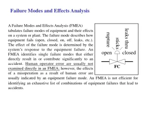
1. PUMP FAILURE MODES
2. PUMPS � SO SIMPLE ? Pumps are probably the most simple piece of machinery in the workplace but the most probable to break down.
This is 99% due to
APPLICATION
+
CONTROL
Good Application and Control will allow a pump to operate for the full design life � Generally 15,000 hr depending upon the specific job
3. BASIC PUMP KILLERS CAVITATION
LACK OF FLUID
REVERSE ROTATION
CYCLING
COUPLING MIS-ALIGNMENT
IMBALANCE
CLOSED HEAD OPERATION
4. CAVITATION
5. CAVITATION Suction Cavitation occurs when the pump suction is under a low pressure/high vacuum condition where the liquid turns into a vapour at the eye of the pump impeller.
This vapour is carried over to the discharge side of the pump where it no longer sees low pressure and is compressed back into a liquid by the discharge pressure. This imploding action occurs violently and attacks the face of the impeller.
An impeller that has been operating under a suction cavitation condition has large chunks of material removed from its face causing premature failure of the pump
6. CAVITATION cav.i.ta.tion \ kav' i ta' shun \ n [1. the rapid formation and collapse of vapor pockets in a flowing liquid in regions of VERY LOW PRESSURE. 2. such a pocket formed.] (Webster)
7. CAVITATION The pump needs to be operating so that the NPSH available is greater than the NPSH required
8. CAVITATION
9. CAVITATION Remedies
1. Remove debris from suction line
2. Move pump closer to source tank/sump
3. Increase suction line diameter
4. Decrease suction lift requirement
5. Install larger pump running slower which will decrease the Net Positive Suction Head Required by the pump(NPSHR)
6. Increase discharge pressure
7. Fully open Suction line valve
10. NPSH Net Positive Suction Head
11. NPSH required NPSHr is be is typically determined by varying the suction head until a 3% drop in Head is noted.
This is a function of each pump and cannot be calculated. It can only be tested by the pump manufacturer.
12. Examples Of Cavitation
13. Vertical multistage pumps with pressed impellers do not exhibit the same failure mode as cast components.
Typical failure is bearing and shaft failure
15. Implosion of Vapor Bubble
16. LACK OF FLUID Whilst obvious this situation can happen easily with multiple pumps on common manifolds. There are two types of fluid loss:
Full fluid loss
Prime loss
Suction line break
Loss of fluid from the source
Partial fluid loss
Air entrapment
Design fault
17. Full Fluid Loss This is generally easy to diagnose as there is no pumping flow at all and the system is in shutdown mode due to protection of low pressure
18. Partial Fluid Loss VERTICAL MOUNTED END SUCTION PUMPS
19. Allow for the trapped air to vent from the impeller area:
Air relief valves
Vacuum pump
20. Air Purge 2 x 110 kW pumps
4 m suction lift
No foot valve
Vacuum prime
Air relief valve on discharge header
Full volute purge
21. Common Manifolds Air entrapment can cause partial prime loss on common manifolds
Install Air Relief valves if possible on each pump at the highest point on the pressure side
22. REVERSE ROTATION Reverse rotation is a basic problem that can occur in any multi pump system.
******* ALWAYS CHECK PUMP ROTATION *******
If it is a VFD system then make sure that you check in both Manual Operation mode and in Automatic Mode
23. ROTATION & VFD SYSTEMS
24. REVERSE ROTATION
25. CYCLING
26. INCREASED RUNNING COSTS
27. INCREASED RUNNING COSTS
28. TRANSMISSION LINE
29. Cycling Failure Hydraulic
Special attention has been given to achieving a robust mechanical design.
Key elements of design
- use of high integrity castings
- larger shaft diameters
- taper connection to impeller
- larger bearing sizes
- sealed for life bearings
- use of mechanical seals as standard
- �O� rings for casing seal and mechanical seal in rubber.
- Both with Viton option
30. COUPLING ALIGNMENT
31. COUPLING ALIGNMENT
32. IMBALANCE
33. Closed Head Operation Operating a pump at NO FLOW or CLOSED HEAD will eventually damage the pump.
It will overheat the fluid in the volute
Possibly cavitate the pump
Generate vapor bubbles in the volute
Many systems operate THROTTLING VALVES that will simulate a closed head or near to Closed head Operation
34. How long at CLOSED HEAD Generally the Rule of Thumb for closed head operation is considered to be 2 minutes but if you need to calculate it use this formula.
Tr = [ (42.4 x HP) / (W x C) ]
where:
Tr = rate of temperature rise, deg F/min
HP= BHP at shut-off
W = weight of liquid in pump case, lbs
C = specific heat of liquid; use 1.0 for water