Download
1 / 15
180 likes | 357 Views
Schematics & Troubleshooting . Automotive service manuals include wiring schematics of all the electrical circuits oaf a vehicle. They may be Combined in several large sheets May be broken down into individual circuits

E N D
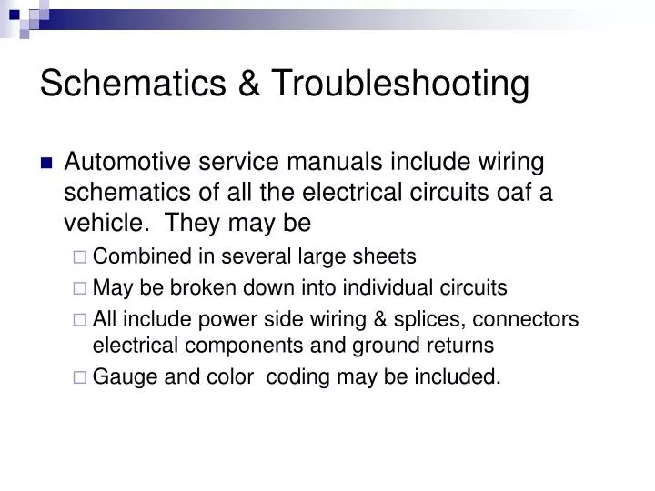
Schematics & Troubleshooting • Automotive service manuals include wiring schematics of all the electrical circuits oaf a vehicle. They may be • Combined in several large sheets • May be broken down into individual circuits • All include power side wiring & splices, connectors electrical components and ground returns • Gauge and color coding may be included.
Color Coding • Most letters used on or near a wire indicate color coding. • The first abbreviation is for the basic color of the wire. • A slash “/” followed by a second abbreviation indicates a color marker and/or stripe on the wire
ABBREVIATION BRN BLK GRN WHT PPL PNK TAN BLU YEL ORN DKBLU LTBLU DKGRN LTGRN RED GRY COLOR Brown Black Green White Purple Pink Tan Blue Yellow Orange Dark blue Light blue Dark green Light green Red Gray Color Coding
Purple Here Purple with a White stripe Here Wire Color Coding Often, wiring will change colors at a connection:
Connector Location (c=connector) Wire Gauge Wire Color Coding Wire gauge and location will also often appear on the schematic.
Switches • Switches are drawn to show their normal position • Normally Closed • Normally Open
Positive / battery side Negative / ground side Connectors • Typically, connectors will show the female portion on the positive side of the circuit.
Switches Single pole, double-throw Single-pole, single-throw Double-pole, double-throw Double-pole, single-throw
86 Power side of coil 87 Normally open out 87a Normally closed out 85 Ground side of coil 30 Common Power in Typical Relay Part of most fog light installation kits
A typical horn circuit. Note that the relay contacts supply the heavy current to operate the horn when the horn switch simply completes a low current circuit to ground to cause the relay contacts to close. Frequently Asked Question TECH TIP
To add additional lighting, simply tap into an existing light wire and connects a relay. Whenever the existing light is turned on, the coil of the relay is energized. The arm of the relay then connects power from another circuit (fuse) to the auxiliary lights without overloading the existing light circuit.
Heat or Movement • Electrical shorts are commonly caused either by movement, which causes the insulation around the wiring to be worn away, or by heat melting the insulation. • When checking for a short circuit, first check the wiring that is susceptible to heat, movement, and damage. • 1. Heat: wiring near heat sources, such as the exhaust system, cigarette lighter, or generator • 2. Wire movement: wiring that moves, such as in such areas near the doors, trunk, or hood • 3. Damage: wiring subject to mechanical injury, such as in the trunk, where heavy objects can move around and smash or damage wiring
Wiggle Test • Intermittent electrical problems are common yet difficult to locate. To help locate these hard-to-find problems, try operating the circuit and then start wiggling the wires and connections that control the circuit. • If in doubt where the wiring goes, try moving all the wiring starting at the battery. Pay particular attention to wiring running near the battery or the windshield washer container. • Corrosion can cause wiring to fail, and battery acid fumes and alcohol-based windshield washer fluid can start or contribute to the problem. • If you notice any change in operation of the device being tested while wiggling the wiring, look closer in the area you were wiggling until the actual problem is located and corrected
To check for an open (break), connect the red lead of the tone generator to the load side of the fuse terminal and the black lead to a good chassis ground. Turn on the transmitter and then listen for the tone signal with the receiver set in the open position. Using a wiring diagram, follow the signal along the circuit until the tone stops, indicating the location of the open.