Download
1 / 91
920 likes | 934 Views
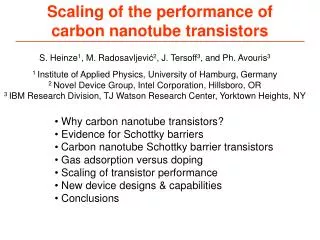
Short Course, 2009 Conference on InP and Related Materials, Newport Beach, CA, May 10-14. Scaling of High Frequency III-V Transistors. Mark Rodwell University of California, Santa Barbara. rodwell@ece.ucsb.edu 805-893-3244, 805-893-5705 fax. THz Transistors.

E N D
Short Course, 2009 Conference on InP and Related Materials, Newport Beach, CA, May 10-14 Scaling of High Frequency III-V Transistors Mark Rodwell University of California, Santa Barbara rodwell@ece.ucsb.edu 805-893-3244, 805-893-5705 fax
THz Transistors Transistor bandwidths are increasing rapidly. Si MOSFETs will soon reach 500+ GHz cutoff frequencies. It is now clear III-V bipolar transistors can reach ~2-3 THz cutoff frequencies. III-V FETs have comparable potential, but the prospects and analysis are less clear. The limits to transistor bandwidth are: contact resistivities gate dielectric capacitance densities. device and IC power density & thermal resistance. challenges in reliably fabricating small devices.
Why Build THz Transistors ? 500 GHz digital logic→ fiber optics THz amplifiers→ THz radios→ imaging, sensing, communications precision analog design at microwave frequencies→ high-performance receivers Higher-Resolution Microwave ADCs, DACs, DDSs
Transistor figures of Merit / Cutoff Frequencies H21=short-circuit current gain MAG = maximum available power gain:impedance-matched fmaxpower-gaincutoff frequency gains, dB U= unilateral power gain:feedback nulled, impedance-matched ftcurrent-gaincutoff frequency
HBT Design For Digital & Mixed-Signal Performance from charge-control analysis: analog ICs have similar bandwidth constraints...
Simple Device Physics: Resistance bulk resistance contact resistance-perpendicular contact resistance- parallel Good approximation for contactwidths less than 2 transfer lengths.
Simple Device Physics: Depletion Layers capacitance transit time space-chargelimited current
Simple Device Physics: Thermal Resistance Exact Long, Narrow Stripe Carslaw & Jaeger 1959 HBT Emitter, FET Gate Square ( L by L ) IC on heat sink
Simple Device Physics: Fringing Capacitance wiring capacitance FET parasitic capacitances VLSI power-delay limits FET scaling constraints
Frequency Limitsand Scaling Laws of (most) Electron Devices PIN photodiode To double bandwidth, reduce thicknesses 2:1 Improve contacts 4:1 reduce width 4:1, keep constant length increase current density 4:1
Bipolar Transistor Scaling Laws Changes required to double transistor bandwidth: Linewidths scale as the inverse square of bandwidth because thermal constraints dominate.
FET Scaling Laws Changes required to double transistor bandwidth: Linewidths scale as the inverse of bandwidth because fringing capacitance does not scale.
THz & nm Transistors: it's all about the interfaces Metal-semiconductor interfaces (Ohmic contacts):very low resistivity Dielectric-semiconductor interfaces (Gate dielectrics):very high capacitance density Transistor & IC thermal resistivity.
Z. GriffithE. Lind Indium Phosphide Heterojunction Bipolar Transistors
Epitaxy: InP Emitter, InGaAs Base, InP Collector, Both Junctions Graded M. DahlstromZ. Griffith UCSB M. UrteagaTSC Key Features: N++ InGaAs emitter contact layer InP emitter InGaAs/InAlAs superlattice e/b grade InGaAs graded base bandgap or doping grade BC setback layer InGaAs/InAlAs superlattice b/c grade InP collector InGaAs etch-stop layer thin for heat conduction InP subcollector emitter collector gradedbase subcollector emittercap
M. DahlstromZ. GriffithE. Lind Epitaxy with Abrupt BE Junction Similar design Abrupt E/B junction (no e/b grade) Advantages:ease of stopping emitter etch on base→ good base contacts Disadvantages:Increased Vbe .Cannot make e/b ledge. emitter collector gradedbase subcollector emittercap
E . LindZ. Griffith Alternative Grades for Thinner Epitaxy Common Grade in LiteratureInGaAs/InAlAs 18 nm thick, 1.5 nm period Sub-monolayer Grade0.15 nm InAlAs, (0.15 to 0.165 nm InGaAs)10.8 nm thick Strained InxGa1-xAs Grade InGaAs/GaAs 6 nm
Other Methods of Grading the Junctions InGaAs/InGaAsP/InP grade InP/GaAsSb/InP DHBT IEDM 2001 - does not need B/C grading - E/B band alignment through GaAsSb alloy ratio (strain) or InAlAs emitter -suitable for MOCVD growth - excellent results
Base Transit Time with Graded Base Dino Mensa
Dino MensaMiguel UrteagaMattias Dahlström Base Transit Time: Grading Approaches Compositional grading: strained graded InGaAs base Doping grading unstrained In0.53Ga0.47As base
T. Ishibashi Collector Transit Time
Space-Charge Limited Current Density → Ccb charging time Collector Depletion Layer Collapse Collector Field Collapse (Kirk Effect) Collector capacitance charging time scales linearly with collector thickness if J = Jmax
T. Ishibashi Current-induced Collector Velocity Overshoot 300 Å InGaAs base 2000 Å InP collector 280 GHz peak ft J=0 J= 8 mA/um2 Nakajima, H. "A generalized expression for collector transit time of HBTstaking account of electron velocity modulation," Japanese Journal ofApplied Physics, vo. 36, Feb. 1997, pp. 667-668
Transit time Modulation Causes Ccb Modulation Camnitz and Moll, Betser & Ritter, D. Root
Emitter-Base Junction Effects Space-charge storage Voltage drops in depletion region Electron degeneracy contributes 1 - μm2equivalent series resistance RodwellLundstrom. need thin layer &high electron density need thin layer to avoid substantial charge storage delays
Simple Device Physics: Resistance bulk resistance contact resistance-perpendicular contact resistance- parallel Good approximation for contactwidths less than 2 transfer lengths.
HBT RC Parasitics base contact width < 2 transfer lengths → simple analysis Limiting case of Pulfrey / Vaidyanathanfmax model.
Device Design Device Scaling
Simple Device Physics: Thermal Resistance Exact Long, Narrow Stripe Carslaw & Jaeger 1959 HBT Emitter, FET Gate Square ( L by L ) IC on heat sink