Download
1 / 1
10 likes | 86 Views
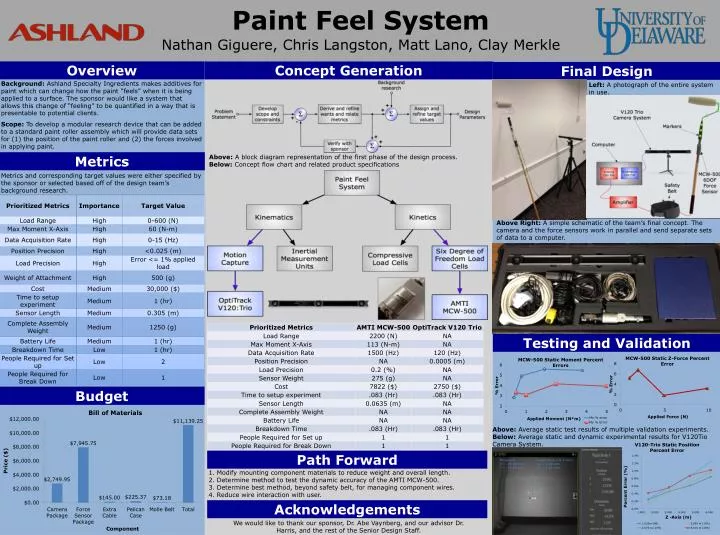
Paint Feel System. Nathan Giguere, Chris Langston, Matt Lano, Clay Merkle. Overview. Concept Generation. Final Design.

E N D
Paint Feel System Nathan Giguere, Chris Langston, Matt Lano, Clay Merkle Overview Concept Generation Final Design Background: Ashland Specialty Ingredients makes additives for paint which can change how the paint “feels” when it is being applied to a surface. The sponsor would like a system that allows this change of “feeling” to be quantified in a way that is presentable to potential clients. Left: A photograph of the entire system in use. Scope: To develop a modular research device that can be added to a standard paint roller assembly which will provide data sets for (1) the position of the paint roller and (2) the forces involved in applying paint. Metrics Above: A block diagram representation of the first phase of the design process. Below: Concept flow chart and related product specifications Metrics and corresponding target values were either specified by the sponsor or selected based off of the design team’s background research. Above Right: A simple schematic of the team’s final concept. The camera and the force sensors work in parallel and send separate sets of data to a computer. Testing and Validation Budget Above: Average static test results of multiple validation experiments. Below:Average static and dynamic experimental results for V120Tio Camera System. Path Forward Measured: Target Value (25.4 mm) X = -15.88 mm ∆X = 4.08 mm Y = -14.28 mm ∆Y = 1.31 mm 1. Modify mounting component materials to reduce weight and overall length. 2. Determine method to test the dynamic accuracy of the AMTI MCW-500. 3. Determine best method, beyond safety belt, for managing component wires. 4. Reduce wire interaction with user. Acknowledgements We would like to thank our sponsor, Dr. Abe Vaynberg, and our advisor Dr. Harris, and the rest of the Senior Design Staff.