Download
1 / 53
530 likes | 537 Views
This reading assignment provides an overview of the CPU12 instruction set, including instructions for loading data from memory into CPU registers, transferring and exchanging data between registers, addition and subtraction instructions, and more.

E N D
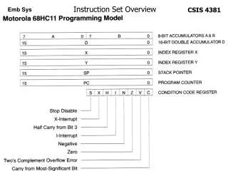
CPU12 Instruction Set Overview Reading Assignment: Huang Ch 4 CPU12 Manual
ORG $4020 Datalist: FCB $12, $34, $44, $46, $78 ORG $4675 FCB $90, $89, $67, $56, $34, #23 ORG $4000 LDY #Datalist LDX 3,Y ;Load $4678 into register X LDX [3,Y] ;Load $5634 into register X LEAX 3,Y ;Load $4023 into register X ;LEAX loads the effective addr ;of the data, not the data itself. LEAS 4,S ;SP + 4 -> SP ;Used to remove 4 bytes from stack! Examples of “Load Effective Address” Instructions
SEX (Sign Extend) Example • SEX B,X ;Sign extend 8-bit nr in B into ;16-bit nr in X • B->XLow and $FF -> XHigh if MSB(B) = 1 • B->XLow and $00 -> XHigh if MSB(B) = 0
TFR Examples TFR A,B ;A -> B TFR B,X ;SEX B -> X TFR B,D ;SEX B ->A:B TFR X,B ;XLow -> B TFR D,SP ;D -> SP
Examples XCHG EXG A,B ;A-> B and B-> A EXG B,A ;B-> A and A -> B (no difference) EXG X,Y ;X -> Y and Y -> X EXG Y,X ;Y -> X and X -> Y (no difference) EXG A,X ;A -> XL and XL -> A, but $00 -> XH EXG X,A ;XL -> A and A -> XL, but $FF -> XH
For multiple-precision addition, use ADDx to add the least significant byte position, and then use ADCx to add the rest of the byte positions, as you work your way up from leas significant byte position to most significant byte position. ORG $0400 RESULT: DS.B 5 ORG $4000 ADDEND: DC.B $12, $34, $56, $78, $98 AUGEND: DC.B $08, $AB, $CD, $EF, $AD Entry: CLRA LDAA ADDEND+4 ADDA AUGEND+4 ;Use “ADDA” when adding least sig. bytes STAA RESULT+4 LDAA ADDEND+3 ADCA AUGEND+3 ;Use “ADCA” (add with carry) STAA RESULT+3 ;when adding all remaining bytes. …. ETC….
ABA, ABX example LDD #$1234 ;D = A:B LDX #$CDEF ABA ;D = $4634 ABX ;D = $CDEF + $0034 ;Thus D = $CE23
Binary Coded Decimal (BCD) Addition Instructions Ex: LDAA #$68 ADDA #$27 A = $8F ;Normal Binary Addition Result DAA A = $95 ;Adjusted BCD Result ($8F+$06=$95) ;Note: DAA adds “6” to least sig 4 bits if H=1 or result > 9 ; and it adds “6” to most sig 4 bits if C = 1 or result > 9
Increment and Decrement Instructions: Note: they affect N, Z, V flags, but not C Flag so they can be used for looping in multiple precision calculations.
Compare and Test Instructions They subtract, set the condition code flags ZNVC. The “difference” result is not stored. These instructions are typically followed by a conditional branch instruction that branches off of the way the resulting flag setting
Compare Example LDAA PTT CMPA #45 BGT OVER_45 ;Branch to “OVER_45” if Port T ;contains a binary value that ;is greater than 45 in a signed ;two’s complement sense. . UNDER_46: NOP …… OVER_45: NOP
Boolean Logic (Bit-by-bit) AND, EOR and OR ANDA #%00010100; Force (mask) all bits in A to 0 except Bits 2 and 4 unchanged. EORA #%00010100; Invert bits 2 and 4, leaving rest of bits unchanged ORAA #%11101011; Force all bits in A to 1 except Bits 2 and 4 unchanged ORCC #%00001011; CCR=SXHINZVC. Force N, V, and C to 1. Rest unchanged.
Multiply & Divide Examples LDAA #4 LDAB #6 MUL ;D = A*B = 24 LDX #10 IDIV ;D = Rmdr(D/X) = 4 ;X = D/X = 2 ; ;Note dividing by 10 breaks an 8-bit binary ;number up into its two decimal digits! LDD #24 LDX #10 FDIV ;X extracts first 16 bits of FRACTIONAL part of D/X ; (D must be < X) ;Note 24/10 = %010.0110011001100110...... ;(0.4 = 1/4+1/8+1/64+1/128 = 0.3987) ;Result of FDIV is X = 0110011001100110 LDD #$FFFF LDY #4 EMUL ;Y*D-> Y:D (unsigned numbers) ;65535*4 = 262140 =>Y = $3, D = $FFFC LDD #$FFFF LDY #4 EMULS ;Y*D -> Y:D (signed numbers) ;-1 * 4 = -4 => Y = $FFFF, D = $FFFC
Arithmetic vs. Logical Shift • Logical shift used for simulating a shift register to serially shift parallel data one bit at a time into, our out of, an I/O pin, or for multiplying or dividing UNSIGNED binary numbers by two. • Arithmetic shift used for multiplying or dividing SIGNED (2’s complement) binary numbers by two. • There are THREE forms of of shifts: shift memory, shift A, shift B Example: (LSL $1000, LSLA, LSLB) • LSL (logical shift left) and ASL (arithmetic shift left) instructions are exactly the SAME: They both shift a zero into the LSB and shift the rest of the bits to the left to multiply a signed number by two. The MSB goes into the carry flag “C”. • Examples: if A = %00000101 = 5, LSLA => A = %00001010 = 10 if A = %11111110 = -2, LSLA => A = %11111100 = -4 if A = %00000101 = 5, ASLA => A = %00001010 = 10 if A = %11111110= -2, ASLA => A = %11111100 = -4
LSR (and ASR) are used to divide unsigned (and signed) numbers by two. To DIVIDE an unsigned number by two, LSR must shift a zero into the MSB, and the rest of the bits are shifted to the right. If A = %00010101 = 21, then LSRA => A = %00001010 = 10 If A = %11111110 = 254, then LSRA => A=%01111111 = 127 BUT to DIVIDE a signed (2’s complement) number by two, ASR must shift the MSB of the number to be shifted, and shift the rest of the bits are shifted to the right. If A = %00010101 = 21, then ASRA => A = %00001010 = 10 If A = %11111110 = -2, then ASRA => A=%11111111 = -1 If A = %11111000 = -8, then ASRA => A =%11111100 = -4 Therefore LSL and ASL are exactly the same instruction (same OP CODE!), but LSR and ASR are different instructions, and hence have different OP CODEs.
Example: 24-bit Shift Left C <- LOC2 <- LOC1 <- LOC0 <- 0 ORG $400 ;Start of RAM LOC2: RMB 1 ;High byte of 24-bit number LOC1: RMB 1 ;Middle byte of 24-bit number LOC0: RMB 1 ;Low byte of 24-bit number ORG $4000 ;Start of Flash ROM …… LSL LOC0 C <- LOC0 <- 0 ROL LOC1 C <- LOC1 <- C ROL LOC2 C <- LOC2 <- C
Fuzzy Logic Instructions HC12 includes high-level instructions tailor made for implementing fuzzy logic controllers
Brief of Overview of Fuzzy Logic Instructions • MEM – Membership Function classifies an input value into a membership class • REV and REVW - Unweighted and weighted min-max rule evaluation • WAV and WAVR – Weighted Average and Resume Weighted Average (after an interrupt)
Min-Max instructions (8 and 16-bit) • MINA $3800 ; puts contents of A or contents of $3800 into A, whichever is smallest in an unsigned sense • EMAXM $3800 ; puts contents of D or contents of $3800:$3801 into $3800:$3801, whichever is larger in an unsigned sense. • EMACS – 16X16 multiply and accumulate instruction, accumulates 32-bit result (useful in digital filter routine or defuzzification routine). • If X = $3900 and Y = $3A00 • EMACS $3800 ; ($3900:$3901) X ($3A00:$3A01) + ($3800:$3803) -> ; $3800:$3803
Bxx – Short Branch Instructions with 8-bit PC Relative Offset
LBxx Long Branch Instructions with 16-bit PC-Relative Offset
; BGE vs BHS example: Finding largest number ; Use BHS for finding largest UNSIGNED nr ($FE) ; Use BGE for finding largest SIGNED nr ($78) XDEF Entry ABSENTRY Entry ORG $0400 ;Start of RAM Greatest: DS.B 1 ORG $4000 ;Start of Flash ROM DataTable: DC.B $12,$AB,$FE,$78,$CD,$00,$10,$FC,$00,$34 LengthTable:EQU 10 Entry: LDX #DataTable LDAA 0,X ;"A" holds greatest value NextElement: CMPA 1,X ;Find greatest UNSIGNED element BHS NoChangeA ;Change to BGE to find greatest ChangeA: ;SIGNED element. Branch if LDAA 1,X ; A>=(1+X) in an UNSIGNED sense! NoChangeA: INX ;Check next element CPX #DataTable + LengthTable - 1 BNE NextElement STAA Greatest ;Should hold "$FE" for BHS above Done: BRA Done ;Should hold "$78" if BHS changed to BGE. ORG $FFFE DC.W Entry ;Or use FDB directive
Bit Condition Branch Instructions • Tests selected bit(s) and branches if selected bit(s) are either 0 or 1 • Syntax: BRSET REG,mm,TARGET(branches to location TARGET if selected bits in “REG” are 1 (for BRSET) or are 0 (for BRCLR). • Bits in REG are selected by the position of the 1’s in the MASK constant “mm”.
Ex: Wait while switch on PT3 is high • 1E 02 40 08 FB WtHr: BRSET PTT,$08,WtHrThis single instruction is equivalent to • B6 02 WtHr: LDAA PTT • 84 08 ANDA #$08 • 26 F9 BNE WtHr • Also note BRSET does not alter “A” or “CCR”
DBNE Example DBNE is used to loop back 8 times through the program, which in this case are simply two NOP instructions CE 00 08 Entry: LDX #8 A7 LoopHr: NOP ;NOPs represent A7 NOP ;things to do 8 times….. 04 35 FB DBNE X,LoopHr “DBNE X,LoopHr” could be replaced by two instructions: DEX BNE LoopHr
Software Interrupt Instruction (SWI) –causes interrupt using the $FFF6:$FFF7 interrupt vector
LEAS example: Transferring arguments into subroutine via the stack Entry: ;Example of a subroutine that adds 3 words ;Whose values are pushed on the stack, ;and the resulting sum is returned in register X lds #$1000 ;RAM block from $0400 - $0FFF ldx #$1234 pshx ;Push input argument #1 ($1234) ldx #$4321 pshx ;Push input argument #2 ($4321) ldx #$2345 pshx ;Push input argument #3 ($2345) jsr add3wordsub leas 6,sp ;clean the 3 input words ;(6 bytes) off of the stack! stx result_sum done: bra done ;*****Subroutine "add3wordsub" starts here (register D is preserved). add3wordsub: pshd ;save D register, since it is altered in this rtn ldd #0 ;Stack Map: 1000 -- addd 8,SP ;(after pshd) 0fff 34 (Arg1_Lo) addd 6,SP ; SP+8-> 0ffe 12 (Arg1_Hi) addd 4,SP ; 0ffd 21 (Arg2_Lo) ; SP+6-> 0ffc 43 (Arg2_Hi) ; 0ffb 45 (Arg3_Lo) ; SP+4-> 0ffa 23 (Arg3_Hi) ; 0ff9 PClow tfr d,x ; 0ff8 PChigh (Return Addr) puld ; 0ff7 Dlow (b) rts ; SP-> 0ff6 Dhigh (a)