Download
1 / 38
440 likes | 502 Views
Overview of Real-Time Computer Graphics. CS 498: Virtual Reality. UNIVERSITY OF ILLINOIS AT URBANA-CHAMPAIGN. Eric Shaffer. 3D Graphics: Image Formation. Goal in CG (usually)is to generate a 2D image of a 3D scene… The input data is a scene description Output is an image

E N D
Overview of Real-Time Computer Graphics CS 498: Virtual Reality UNIVERSITY OF ILLINOIS AT URBANA-CHAMPAIGN Eric Shaffer
3D Graphics: Image Formation • Goal in CG (usually)is to generate a 2D image of a 3D scene… • The input data is a scene description • Output is an image • One approach is to computationally mimic a camera or human eye • In the scene…there are objects…lights…and a viewer
“Chlorophyll” Light is EM radiation Usually multiple wavelengths mixed together in a power spectrum The spectrum sensed by our eyes gets modified multiple times. Human perception of color relies on 3 different cell types that sense different regions of the spectrum
Synthetic Camera Model How can we computationally mimic a camera? What specific data would you need? What specific computations would you perform?
Polygonal Models Our digital representation of a scene will primarily use polygonal models
Rendering or image synthesis is the automatic process of generating a photorealistic or non-photorealistic image from a 2D or 3D model • Rendering methods generally use one of two approaches • Rasterization (focus of CS 418) • Ray Tracing (focus of CS 419) • Though, sometimes you can use both…. • …and the are other methods like radiosity By Gilles Tran - http://www.oyonale.com/modeles.php?lan
Rasterization versus Ray Tracing • To oversimplify…. • In rasterization, geometric primitives are projected onto an image plane and the rasterizer figures out which pixels get filled. • In ray-tracing, we model the physical transport of light by shooting a sampling ray though each pixel in an image plane and seeing what the ray hits in the scene
Ray Tracing Follow ray of light…. Can trace from an eyepoint through a pixel See what object the ray hits… How would you check to see if the object is lit?
Rasterization For each primitive: Compute illumination Project to image plane Fill in pixels
Global versus Local Illumination For true photo-realism:We cannot compute color or shade of each object independently Why?
Some objects are blocked from light Light can reflect from object to object Some objects might be translucent Can rasterization produce global lighting effects? Can ray tracing? The big advantage of rasterization is…?
Rasterization Engines • Most low-level graphics libraries use a camera model • API typically requires you to specify • Objects in the scene • Materials the objects are made of • Viewer (position, view direction, field of view,…) • Lights - what parameters do you think typically are used? • The engine (i.e. the library) will use pipeline-style processing • The input geometry flows through several processing stages API = Application Programming Interface
Definitions: Pixel and Raster A pixel is the smallest controllable picture element in an image A raster is a grid of pixel values Typically rectangular grid of color values (1.0, 0.0, 0.0), (0.0, 0.0, 1.0) (0.0, 0.0, 1.0), (1.0, 0.0, 0.0) RGB Color Representation A color is a triple (R,G,B) representing a mix of red, green, and blue light. Each color channel has a value in [0, 1] indicating how much light is emitted.
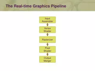
VertexProcessing FragmentProcessing 3D Graphics Pipeline Rasterization Fragments Are like pixels…but they aren’t necessarily the finalized pixels you see in an image. Each fragment has a 2D location in a raster and a color.Final pixel value is typically found by applying hidden surface removal and possibly compositing to a set of fragments.
Rasterization is a Pipeline • Data for objects in the scene usually in the form of polygonal meshes • Most of the work to render an image is done on the Graphics Processing Unit (GPU) • GPU code will have at least two parts • Vertex Shader • Fragment Shader
Changing Coordinate Systems Model Transformation:Move a model from a local coordinate system to a position in the “world” View Transformation: Keeping camera fixed, move all the objects in the world so that they are seen as if from a specific viewpoint Projection Transformation:Change coordinates so that a 3D to 2D projection of the geometry is done correctly Viewport Transformation:Change from 2D coordinates in [-1,1] to pixel coordinates
Modeling Transformation • Pretty simple…models are create in model coordinates • Often centered on the origin • A Modeling Transformation • moves the model into the correct spot in the World • It can be any combination of affine transformations In this diagram, replace “camera transformation” with “view transformation”. And “camera space” is “view space”
Viewing We often will want to allow the view of our 3D scene to change We can do so using by applying affine transformations to the geometry A view matrix is functionally equivalent to a camera It is a transformation matrix like the Model matrix, but • Happens after the modeling transformation • It applies the same transformations equally to every object • Moving the whole world 5 units towards us = walking 5 units forwards “The engines don’t move the ship at all. The ship stays where it is and the engines move the universe around it.” -- Futurama
Example From WebGL Beginner’s Guide by Cantor and Jones
Graphics Pipeline ModelCoords ModelXform WorldCoords ViewingXform ViewingCoords PerspectiveDistortion StillClipCoords. Clipping ClipCoords. Homogeneous Divide Window Coordinates Window to Viewport Viewport Coordinates
Graphics Pipeline ModelCoords ModelXform WorldCoords ViewingXform ViewingCoords PerspectiveDistortion StillClipCoords. Clipping ClipCoords. Homogeneous Divide M Window Coordinates Window to Viewport Viewport Coordinates
Viewing Transformation ModelCoords ModelXform WorldCoords ViewingXform ViewingCoords PerspectiveDistortion StillClipCoords. Clipping ClipCoords. Homogeneous Divide Window Coordinates Window to Viewport Viewport Coordinates
Viewing Transformation eyepoint lookatpoint y y x x z ScreenCoords ClipCoords ViewingCoords WorldCoords ModelCoords
Creating a Camera Function Suppose we want to implement a function that sets up view …think of it as setting up a camera There are lots of possible ways to do this…we’ll choose a simple lookat camera The API we create will require a someone using the function to specify: • The eyepoint(or camera location) • The lookat point (a point in the view direction) • An ”up” vector that we use to specify rotation around the view vector
Deriving the Viewing Transformation One way to think about what you are doing • Translate the eyepoint to the origin • Rotate so that • lookat vector aligns with –z axis • up aligns with y We move all objects (the world) this way… • Another way to think of it • Create an orthonormal basis with eye at the origin • And vectors u, v, w as the basis vectors • …and then align u,v,w with x,y,z
Constructing a Local Frame A frame has an origin point and set of basis vectors Any point can be expressed as coordinates in such a frame For example (0,0,0) and <1,0,0>, <0,1,0>,<0,0,1> • And an example of a point in that space: (4,0,0)= (0,0,0) + 4 <1,0,0> + 0 <0,1,0> + 0 <0,0,1>
Cross Product of Two Vectors Important Property: The cross product yields a vector orthogonal to the original two vectors
The Orthonormal Basis for View Space This derivation assumes an right-handed coordinate system and view down the –z axis…how could we change it to look down +z? • Let be the lookat vector…then • If is the up direction • And then • The view matrix is then: Why is the matrix inverted?
View Transformation is referred to as the camera matrix or transformation. is the view transformation or matrix You can now look at your scene from any • Position • Orientation (almost) • What lookat and up vector pair won’t work? …just uses a matrix multiplication
Let’s review the rasterization pipeline We start out by setting up our geometry in world coordinates Which transformation does this?
The view transformation We pick a specific viewing position and direction in worldspace
The view transformation Actually…in Unity we use a lefthanded coordinate system and look down the +z axis We transform the world so the view position is at the origin.For a right-handed coordinate system, the view direction is down the –z axis
The projection transformation We pick a viewing volume. This is specified in viewing coordinates.
The projection transformation The WebGL view volume is a box with clip planes at -1, +1 The z coordinates are negated to flip the z-axis Our view volume is transformed to fit in the canonical view volume. Is this actually a projection?
Actual projection…. The rasterization engine does an orthographic projection of the view volume contents to 2D
The viewport transformation • Moves from 2D canonical coordinates • x in [-1,1] and y in [-1,1] • To viewport coordinates • Integer pixel coordinates • We can do this! • What affine transforms do we need?