Download
1 / 32
320 likes | 328 Views
DC Circuits Review, Part 1 and 2 February 2016. The must know subjects Voltage V, Current I, Power P and Circuit Diagram Exercise examples and 2 Quizzes Resistivity ρ, Resistance R, Ohm ’ s Law Ω and Circuit Diagram Exercise examples and Quizzes

E N D
DC Circuits Review, Part 1 and 2 February 2016 The must know subjects Voltage V, Current I, Power P and Circuit Diagram Exercise examples and 2 Quizzes Resistivity ρ, Resistance R, Ohm’s Law Ω and Circuit Diagram Exercise examples and Quizzes Kirchhoff’s Law, Resistance in Series and Parallel Exercise examples and Quiz Demonstration with Quizzes Electric field E, Electric charge q, Coulomb’s Law and Electric Field Force F Exercise examples and Quizzes
Electric Power I R When the switch closes electric current flows and electrons are given energy by the battery voltage. The carriers of the circuit charge, q pass through the resistor, R and collide with resistor atoms losing energy. Any charge carrier loses all the potential energy it gained from the battery by the time it returns to the battery. The electric energy transferred in the collisions can increase resistor’s temperature and becomes transformed into thermal energy. Electrical energy can be transformed also into other useful forms such a light or mechanical work (Law of conservation!) Energy of electric charge, Eq = qV Average rate of energy delivered by the battery or electric power P = qV/t = IV [W] Thermal energy expended in a current-carrying resistor is a power loss Pl = I2 R
The “must know” equations Itot Resistance: R = ρ L/A [Ωm(m/m2)] Ohm’s Law:R = V/I [V/A] V = RI [V = ΩA] Power: P = VI [W=VA] P = RI2 [W = ΩA2] Energy: E = Pt [J = Whr] Resistance in Series: R = R1 + R2 Resistance in Parallel: R = (R1 x R2)/(R1 + R2) R1 I1 I2 R2 V
Resistors in Series Itot I R1 R1 V1 I1 I2 V R2 V2 Resistors in Parallel V R2 Three Minute Exercises follow!
Exercises with Answers 1.B, 2.B, 3.A, 4.B, 10.A, 11.E, 12.E, 17.D, 18.C, 19.A, 20.B, 21.
Kirchhoff’s Junction Theorem Applied Resistors in Parallel, Rp Application of the Kirchhoff’s Junction Theorem which states that in an electric current junction the sum of all currents is equal to zero. Ip = !1 + I2 + I3 But I = V/R Vp/Rp = V1R1 + V2/R2 + V3/R3 But Vp = V1= v2 = V3 Then by cancelling V the equation becomes 1/Rp = 1/R1 + 1/R2 + 1/R3 Rp = (R1 x R2)/(R1 + R2) V R1 R2 R3 Ip I2 I3 !1 Example: R1 = 4Ω ; R2 = 6 Ω ; Rp = ? Ω The total resistance is ______ than the smallest resistance in a parallel circuit arrangement because the ______ remains the same. 15
Kirchhoff’s Loop Theorem Applied Resistors in Series, Rs Application of the Kirchhoff’s Loop Theorem which states that in a closed loop the sum of all voltages is equal to zero, Vs - V1 - V2 - V3 = 0 Is Vs = V1 + V2 + V3 ; V = IxR by Ohm’s Law, therefore Vs = IsRS = ISR1 + ISR2 + ISR3 and because Is = I1 = I2 = I3 we conclude that R1 = R1 + R2 + R3 Example: R1 = 5 Ω R2 = 10 Ω V = 12 V Rs = R1 + R2 = 15 Ω R1 V1 + Vs R2 V2 - - V3 R3 The total resistance must be _____ than the largest resistance in a series circuit arrangement because the ______ remains the same.
What is the emf of a battery? Use the Kirchhoff’s Loop Rule! • Vemf = ? • = V1 + V2 //3 + V int • = R1 I + R2//3 x I + Rint xI • = (30 + 30 + 6) x .2 • = 13.2 V • Vxy = Vemf – Rint x I = 13.2 – 6x.2 = 12 V • Pxy = Vxy x I = 12x.2 [VA] = 2.4 W
Benjamin Franklin’s Experiment (1706----1790) KITE After failing to exploit the energy of lightning Benjamin Franklin devised the lightning rod, an iron rod attached to the highest point of a structure and connected to wires leading to the ground.
When the lightening strikes Barstow airport, California 2015
Charles-Augustin de Coulomb (1786----1806) Following Franklin’s work, electrical research advanced by leaps. Quantitative measurements were carried out in 1785 by the French physicist Charles de Coulomb. He showed that attraction (or repulsion) between given (electric) charges, q varied inversely as the square of their distance from each other. It became known as the Coulomb’s Law between two points, r in an electric field: F = k(q1 x q2)/r2 ; k = 9.00 x10⁹ Nm2/C2 What are the electric charges? What is an electric field?
Electric Charge and Electric Field The electric charge q, is a fundamental property of matter. It is associated with particles that make up the atom: electron and proton. Electron charge e-- = -1.60 x 10⁻¹⁹ C. Proton +e = 1.60 x 10⁻¹⁹ C. Neutron has 0 C. The SI unit of electric charge is the Coulomb C; [C = As]. It is equal to the charge of approximately n =6.241×10¹⁸electrons. Proton’s mass is 104 times larger than the mass of an electron. q = ne– [C or As](Eq 3-1) An electric field E [V/m],is the region of space surrounding electrically charged particles, q[As] and where electric charges are acted upon by an electric force F = Eq [N]. E = F/q [V/m] (Eq 3-2) F = Eq [(V/m) As] = [VAs/m] = [Ws/m] = [N] Why is q-- = -1 C? A: q = ne- = 6.241×10¹⁸ x (-1.6x10⁻¹⁹ C) = -9.9856x10-1 = -1 C = -1 As Electric charges can be activated by electrostatic action
Coulomb’s Law and Electric Force Following Benjamin Franklin’s work, electrical research advanced by leaps. Quantitative measurements were carried out in 1785 by the French physicist Charles-Augustin de Coulomb (1786----1806). He showed that attraction (or repulsion) between given (electric) charges, q varied inversely as the square of their distance, r from each other. It became known as the Coulomb’s Law where Electric force, F between two electric charges between two points is: F = k(q1 x q2)/r2 ; k = 9.00 x10⁹ Nm2/C2 (Eq 3-3) Example: Two point charges q1 = -1 nC and q2 = +2 nC; distance, r between them is 0.30 m. What is the electric force, F on each particle? A: F = 9.00 x 10⁻⁹ Nm2/C2 x (1x10-9 C x 2x10-9 C)/0.09 m2 = 18.0 x 10⁻⁹ N/0.09 = 18.0 x 10⁻⁹ N/9x 10-2 = 0.20 x 10⁻⁶ N; F = 0.20 μN F12 0.30m F21
Positive and negative lightning On Earth, the lightning frequency is approximately 40–50 times a second or nearly 1.4 billion flashes per year and the average duration is 30 microseconds. CG lightning can occur with both positive and negative polarity. The polarity is that of the charge in the region that originated the lightning leaders. An average bolt of negative lightning carries an electric current of 30,000 amperes (30 kA), and transfers 15 coulombs of electric charge and 500 megajoules of energy. Large bolts of lightning can carry up to 120 kA and 350 coulombs. Unlike the far more common "negative" lightning, positive lightning originates from the positively charged top of the clouds (generally anvil clouds) rather than the lower portion of the storm. Leaders form in the anvil of the cumulonimbus and may travel horizontally for several miles before veering towards the ground. A positive lightning bolt can strike anywhere within several miles of the anvil of the thunderstorm, often in areas experiencing clear or only slightly cloudy skies; they are also known as "bolts from the blue" for this reason. Positive lightning typically makes up less than 5% of all lightning strikes. Because of the much greater distance to ground, the positively charged region can develop considerably larger levels of charge and voltages than the negative charge regions in the lower part of the cloud. Positive lightning bolts are considerably hotter and longer than negative lightning. They can develop six to ten times the amount of charge and voltage of a negative bolt and the discharge current may last ten times longer. A bolt of positive lightning may carry an electric current of 300 kA and the potential at the top of the cloud may exceed a billion volts — about 10 times that of negative lightning. During a positive lightning strike, huge quantities of extremely low frequency (ELF) and very low frequency (VLF) radio waves are generated. As a result of their greater power, as well as lack of warning, positive lightning strikes are considerably more dangerous. At the present time, aircraft are not designed to withstand such strikes, since their existence was unknown at the time standards were set, and the dangers unappreciated until the destruction of a glider in 1999. The standard in force at the time of the crash, Advisory Circular AC 20-53A, was replaced by Advisory Circular AC 20-53B in 2006, however it is unclear whether adequate protection against positive lightning was incorporated. Aircraft operating in U.S. airspace have been required to be equipped with static discharge wicks. Although their primary function is to mitigate radio interference due to static buildup through friction with the air, in the event of a lightning strike, a plane is designed to conduct the excess electricity through its skin and structure to the wicks to be safely discharged back into the atmosphere. These measures, however, may be insufficient for positive lightning.
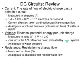
New Terminology • DC: Direct Current • The electrons flow in one direction only. By convention the current flow is positive to negative. • Voltage: Unit is Volts, Symbol is V • Voltage is the "pressure" of electricity. A 6V battery has a voltage of 6V DC, and may be positive or negative depending on the terminal that is used as the reference. The city mains has a voltage of 220 or 110V. This is AC, and alternates between positive and negative values. • Current: Unit is Amperes (Amps), Symbol is I • Current is the flow of electrons. No current flows between the terminals of a battery or other voltage supply unless a load is connected. The magnitude of the current is determined by the available voltage, the resistance of the load and the power source. • Resistance: Unit is Ohms, Symbol is R or Ω • Resistance is a measure of how easily electrons will flow through the device. Copper wire has a very low resistance, so a small voltage will allow a large current to flow. Likewise, the plastic insulation has a very high resistance. • Diode: Semiconductor • A diode is an engineered semiconductor. It consists of two doped materials (one N and one P type), joined together forming a junction which allows it to function as a conductor in one direction and an insulator in the opposite direction. An impurity is added (doping) creating a surplus (N-type) or deficiency (P-type) of free electrons. The P-N junction conducts or not depending on the electrical connection. P (anode) to battery (+) and N (Cathode) to battery (–) conducts current. • Capacitor: An electronic component that can store and release energy. A capacitor passes AC, but will not pass DC once charged. • Capacitance: Unit is Farad, Symbol is C; • Capacitance is a measure of capacitor’s stored charge. Unlike a battery, a capacitor stores a charge electrostatically rather than chemically and reacts much faster. • Electric Field: Unit is Volt V • Itis the region of space surrounding electrically charged particles. • Dielectric: Dielectricis an insulator that can be polarized by the action of an applied electric field. • Permittivity: It relates to material’s ability to transmit (or permit) an electric field. • Polarization: The polarizationtakes place in an applied electric field when molecules of a dielectric material orient along the field poles and retain the electric charge after an external voltage was removed. • Steady State and Transients; • Transients are events that change with time while the steady state is an event that does not change with time.
SI Electromagnetism Units Symbol Name Unit SI Conversion C Capacitance F, Farad As/V I Electric current Ampere A = C/s q Electric charge Coulomb C = As F Farad Capacitance As/V E Electromotive force, Potential difference Volt J/C = (kgms2/A)/s3 ρResistivity Resistivity mΩ P Electric power Watt W = kgms2/s3 E Electric field strength Volt per meter V/m H Magnetic field strength Ampere per meter A/m B Magnetic flux density, Induction (F/qv) Tesla T = Wb/m2 μ Permeability henry per meter Tm/A= H/m = kgm/(As) μ0 Permeability of free space 4 π x 10-7N/A2 F Force of motion N 1 N = 1 kg m/s2 v Velocity m/s Resistance Ohm V/A = 1 Ω = 1 kg·m2·s-3·A-2 in Inch Inch 0.0254 m or 25.4 mm T Tesla Tesla Vs/m2 = N/Am = Wb/ms2 N Newton Newton Kgm/s2 Wb Weber Weber 1 V·s = 1 T·m2 = 1 J/A; J Joule1Nm; 1kgm2/s2 ; 2.78 x 10⁻⁷ kWh; 2.39 x 10⁻⁴ kcal; 9.48 x10⁻⁴ BTU P Mechanical power 1hp 550 ft-lb/s = 1 W Kg Kilogram mass 1.0 kg x 9.8m/s2 1N 32