Download
1 / 33
740 likes | 1.23k Views
CCNA 3 v3.0 Module 7 Spanning-Tree Protocol. Cisco Networking Academy. Spanning-Tree Objectives. Redundant Topologies Spanning-Tree Protocol. Redundancy. Redundant networking topologies are designed to ensure that networks continue to function in the presence of single points of failure.

E N D
CCNA 3 v3.0 Module 7 Spanning-Tree Protocol Cisco Networking Academy
Spanning-Tree Objectives • Redundant Topologies • Spanning-Tree Protocol
Redundancy Redundant networking topologies are designed to ensure that networks continue to function in the presence of single points of failure.
Redundant Topologies • A goal of redundant topologies is to eliminate network outages caused by a single point of failure. • All networks need redundancy for enhanced reliability. • However, transparent bridging begins to have problems when redundant paths are added to the Layer 2 network.
Unknown Unicast Media Access Control Database Instability In a redundant switched network, it is possible for switches to learn the wrong information. A switch can learn that a MAC address is on a port when it is not.
Broadcast Storm 2/1 1/1 1/2 2/2 The process of continually propagating a broadcast is known as a broadcast storm which will eventually bring the network down when the switches’ processor utilization reaches 100%.
L2 Loops • Broadcasts and Layer 2 loops can be a dangerous combination. • Ethernet frames have no TTL field. • After an Ethernet frame starts to loop, it will probably continue until someone shuts off one of the switches or breaks a link. • Ethernet switches associate the source MAC in the Layer 2 header with the a port number
Spanning-Tree Protocol (STP) • STP is a loop-prevention protocol. • allows L2 devices to communicate with each other to discover physical loops in the network. • specifies an algorithm that L2 devices can use to create a loop-free logical topology. • creates a tree structure of loop-free leaves and branches that spans the entire Layer 2 network.
STP Prevents Loops • The purpose of STP is to avoid and eliminate loops in the network by negotiating a loop-free path through a root bridge. • STP determines where the are loops and blocks links that are redundant. • Ensures that there will be only one active path to every destination.
Spanning-Tree Algorithm • STP executes an algorithm called STA (Spanning-Tree Algorithm). • STA chooses a reference point, called a root bridge, and then determines the available paths to that reference point. • If more than two paths exists, STA picks the best path and blocks the rest. • How does STP learn the network topology?
Spanning-Tree BPDUs • All switches using STP must exchange Bridge Protocol Data Units with other switches. • Sent every 2 secondsonevery active port.
BPDUs The exchange of BPDU messages results in the following: • The election of a root switch • The election of a designated switch for every switched segment • The removal of loops in the switched network by placing redundant switch ports in a backup state
BPDUs Bridge protocol data unit (BPDU)
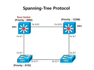
Bridge ID • Consists of two components: • A 2-byte priority: Cisco switch defaults to 32,768 or 0x8000. • A 6-byte MAC address • Used to elect a root bridge. • Lowest Bridge ID is the root. • If all devices have the same priority, the bridge with the lowest MAC address becomes the root bridge -- Yikes!!!
Spanning-Tree Operation 802.1d • One root bridge per network. • One root port per nonroot bridge. • One designated port per segment. • Nondesignated ports are unused.
Root Port • Root Port: The port receiving the best BPDU on a bridge is the root port. • This is the port that is the closest to the root bridge in terms of path cost • The root bridge sends BPDUs that are more useful than the ones that any other bridge can send. • The root bridge is the only bridge in the network that does not have a root port.
Designated Port • A port is designated if it can send the best BPDU on the segment to which it is connected. • On a given segment, there can be only one path toward the root bridge otherwise redundant paths would create a bridging loop. • All bridges connected to a given segment listen to each other's BPDUs and agree on the bridge sending the best BPDU as the designated bridge for the segment.
Spanning-Tree Link Costs Shortest path is based on cumulative link costs. Link costs are based on the speed of the link.
Spanning-Tree Port States These values have been calculated on an assumption that there will be a maximum of seven switches (diameter of seven) in any branch of the spanning tree from the root bridge.
Spanning-Tree Port States • The Max Age allows topology change information to propagate from one side of the network to the other. • In the listening state, switches determine if there are any other paths to the root bridge and pathcostis compared. • In the learning state user data is not forwarded, but MAC addresses are learned from any traffic that is seen. • In the forwarding state user data is forwarded and MAC addresses continue to be learned.
Root port Root port Spanning-Tree Recalculation A switched internetwork has converged when all the switch and bridge ports are in either the forwarding or blocked state. Convergence on a new spanning-tree topology using the IEEE 802.1D standard can take up to 50 seconds.
Spanning-Tree Recalculation • During the time that the Layer 2 network is converging, MAC addresses that can no longer be reached still exist in the CAM table. • STP topology change process forces the switch to purge MAC addresses in the CAM table faster. • When a root bridge sends out a topology change BPDU the topology change is set to a period of time equal to the sum of the max age and fwd delay timers (50 seconds). • A switch receiving the topology change BPDU uses the fwd delay timer (15 seconds) to age out entries in its MAC address table – the default time is five minutes.
Rapid Spanning-Tree Protocol (RST) • The IEEE 802.1w LAN standard and protocol introduce the following: • Clarification of new port states and roles • Definition of a set of link types that can go to forwarding state rapidly • Allowing switches, in a converged network, to generate their own BPDUs rather than relaying root bridge BPDUs
Rapid Spanning-Tree • According to the 802.1w standard: • The “blocked” state of a port has been renamed as the “discarding” state. • A role of a discarding port is an “alternate port”. • The discarding port can become the “designated port” in the event of the failure of the designated port for the segment. • Link types have been defined as point-to-point, edge-type, and shared.
Alternate and Backup Ports • These two port roles correspond to the blocking state of 802.1d (discarding MACs). • A blocked port is defined as not being the designated or root port. • A blocked port receives a more useful BPDU than the one it would send out on its segment. • An alternate port is a port blocked by receiving more useful BPDUs from another bridge. • A backup port is a port blocked by receiving more useful BPDUs from the same bridge it is on.
New BPDU Format • BPDU are sent every hello-time, and not simply relayed anymore. • With 802.1d, a non-root bridge would only generate BPDUs when it received one on its root port. • Actually, every bridge only relays the root bridge’s BPDU • With 802.1w, every bridge generates it’s own BPDU even if it does not receive one from the root bridge. • The Rapid Spanning-Tree Protocol, IEEE 802.1w, will eventually replace the Spanning-Tree Protocol, IEEE 802.1D.
Rapid Spanning-Tree Port Designations The Rapid SpanningTree Protocol, IEEE 802.1w, will eventually replace the SpanningTree Protocol, IEEE 802.1D.