Download
1 / 31
501 likes | 2.43k Views
Sleeve-Metering Rotary Distributor Pumps Chapter 24. DSL 131. OBJECTIVES. Identify the main components of a sleeve-metering, distributor injection pump. Describe the operating principles of a sleeve-metering, distributor injection pump.

E N D
OBJECTIVES • Identify the main components of a sleeve-metering, distributor injection pump. • Describe the operating principles of a sleeve-metering, distributor injection pump. • Explain how fuel is routed, pumped, and metered from the fuel pump to the injector during a sleeve-metering, distributor injection pump cycle. • Outline the circuits in a sleeve-metering, distributor injection pump. • Describe the operating principles of a Bosch VE rotary injection pump. • Identify Bosch VE electronically-controlled rotary distributor pump systems. • Trace fuel flow routing from tank to injector on electronically-controlled, rotary distributor pump fueled diesel engines. • Identify Bosch Electronic Diesel Control (EDC) system components used to manage rotary distributor pump injection systems.
INTRODUCTION • In the days before electronic engine management systems , a significant disadvantage of port-helix metering injection pumps was up-front cost due to its requirement for close tolerance manufacture and a pump/metering element for each cylinder on the engine. • In the quest for lower-cost alternatives, manufacturers looked at rotary distributor pumps which used a single pump element in combination with a distributor head to fuel all the engine cylinders.
INTRODUCTION (Cont.) • Among the advantages offered by rotary distributor injection pumps are: • Lower up-front cost • Simple disassembly and reassembly (for purposes of cleaning) not requiring costly calibration equipment • Hard value phasing of injection pulse not influenced by wear • Balanced cylinder fueling
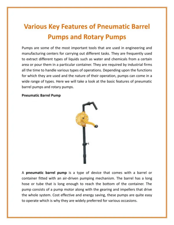
SLEEVE-METERING, SINGLEPLUNGER DISTRIBUTOR PUMPS • Bosch hydromechanical, sleeve-metering distributor injection pumps use a single plunger pumping element. • In describing this technology, the popular VE pump is used as our primary reference.
SLEEVE-METERING, SINGLEPLUNGER DISTRIBUTOR PUMPS • A VE pump has four primary circuits: • Fuel-supply pump • High-pressure pump • Governor • Variable timing
SUBASSEMBLIES • All movement through the fuel subsystem is the responsibility of a vane-type transfer pump integral with the VE pump assembly.
SUBASSEMBLIES (Cont.) • The VE distributor pump housing contains the following subcircuits: • High-pressure (injection) pump with distributor • Mechanical (flyweight) governor • Hydraulic timing device • Vane-type fuel supply pump • Shutoff device • Engine-specific add-on modules
Interaction of Fuel Supply Pump, Pressure Control Valve, and Overflow Restriction Valve
Schematic of How Output Algorithms Are Mappedin a Typical Bosch EDC-Managed VE Pump
Partial Authority VE Distributor InjectionPump Adapted for Electronic Control
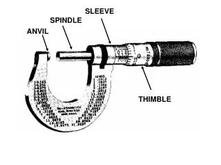
SUMMARY • The main components of a Bosch sleeve-metering, distributor injection pump are: • Vane-type transfer pump • Cam plate • Single plunger–actuated pump chamber • Distributor head • Delivery valves • Control sleeve • Governor assembly • Advance mechanism
SUMMARY (Cont.) • A sleeve-metering, distributor injection pump uses axial movement of a sleeve on the pumping plunger to alter the effective pumping stroke. • The plunger both rotates and reciprocates to pressurize and distribute fuel to outlets in the distributor head.
SUMMARY (Cont.) • Movement of fuel through the fuel subsystem in a sleeve-metering, distributor injection pump is the responsibility of a vane-type transfer pump. • Actual pump plunger stroke is defined by the actuating cam geometry. • The position of the metering or control sleeve determines the actual fuel pumped.
SUMMARY (Cont.) • EDC-managed VE injection pumps use hydraulic injectors with pintle nozzles. • Sometimes these pintle nozzles are equipped with nozzle valve motion sensors (NVMSs).
SUMMARY (Cont.) • An NVMS consists of a coil and nozzle valve-actuated pressure pin. • Movement of the nozzle valve-actuated pressure pin through the coil winding changes the coil reluctance, inducing a signal voltage proportional to the valve’s speed of movement.
SUMMARY (Cont.) • The NVMS enables the ECU to determine the precise moment of start of injection, which helps build the algorithms required for injection timing and EGR management. • The key actuator circuit components in a partial authority, VE pump are the control sleeve solenoid (controls effective pump stroke/fuel quantity) and the start-of-injection solenoid valve (controls timing).
Any Questions ? • Thank You !