Download
1 / 66
680 likes | 871 Views
SMART DUST. B. Boser, D. Culler, J. Kahn, K. Pister Berkeley Sensor & Actuator Center Electrical Engineering & Computer Sciences UC Berkeley. Outline. History Technology Ramblings. Motivation. Exponential decrease in size, power, cost Digital computation Analog/RF communication

E N D
SMART DUST B. Boser, D. Culler, J. Kahn, K. Pister Berkeley Sensor & Actuator Center Electrical Engineering & Computer Sciences UC Berkeley
Outline • History • Technology Ramblings
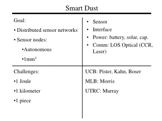
Motivation • Exponential decrease in size, power, cost • Digital computation • Analog/RF communication • Sensors battery Goals • Understand fundamental limits • Build working systems
Moore’s Law, take 2 • Nanochips on a dime (Prof. Steve Smith, EECS)
DoD Workshops • RAND 1992 • “Future Technology-Driven Revolutions in Military Conflict” • “Smart Chaff”, “Floating Finks” • Bruno Augenstein, Seldon Crary, Noel Macdonald, Randy Steeb, … • Santa Fe, 1995 • Xan Alexander, Ken Gabriel; Roger Howe, George Whitesides, … • ISAT 1995, 1996, 1997, 1998, 1999, 2000 • …
University Programs (old slide) • UCLA • Bill Kaiser (LWIM, WINS) • Greg Pottie (AWAIRS) • U. Michigan • Ken Wise • USC • Deborah Estrin • UCB • K. Pister (Smart Dust) • …
Ken Wise, U. Michigan • http://www.eecs.umich.edu/~wise/Research/Overview/wise_research.pdf
Bill Kaiser, UCLA • http://www.janet.ucla.edu/WINS
N W E S 2 Axis Magnetic Sensor 2 Axis Accelerometer Light Intensity Sensor Humidity Sensor Pressure Sensor Temperature Sensor COTS Dust - RF Motes • Simple computer • Cordless phone radio • Up to 2 year battery life
COTS Dust GOALS: • Create a network of sensors • Explore system design issues
COTS Dust RESULTS: • TinyOS – David Culler, UCB • Manufactured by Crossbow ~ $150 • 100+ users, 40+ locations • Military and civilian applications
800 node demo at Intel Developers Forum 4 sensors $70,000 / 1000 Concept to demo in 30 days!
Structural performance due to multi-directional ground motions (Glaser & CalTech) . Mote infrastructure Mote Layout 14 5 ` 15 15 13 6 12 9 11 8 Comparison of Results Wiring for traditional structural instrumentation + truckload of equipment
Cory Energy Monitoring/Mgmt System • 50 nodes on 4th floor • 5 level ad hoc net • 30 sec sampling • 250K samples to database over 6 weeks
29 Palms Sensorweb Experiment • Goals • Deploy a sensor network onto a road from an unmanned aerial vehicle (UAV) • Detect and track vehicles passing through the network • Transfer vehicle track information from the ground network to the UAV • Transfer vehicle track information from the UAV to an observer at the base camp.
Dragon Wagon HMMWV HMMWV From UAV Dragon Wagon From UAV
Last 2 of 6 motes are dropped from UAV • 8 packaged motes loaded on plane • Last 2 of six being dropped
Detection algorithm • Each vehicle V(v,t) has two parameters: • Speed (v) • Time at beginning of network (t) • The n-node network is described by an n-entry pattern vector p: • The jth entry is the time we expect that node j will see V(1,0) • Times when nodes detect V are collected in the t vector Linear least-squares guess at v and t
RF Sensitivity • Pn = kBT Df Nf • Sensitivity = Pn + SNRmin • e.g. GSM (European cell phone standard), 115kbps kBT 200kHz ~8x SNR S = -174dBm + 53 dB + 9 dB + 10 dB = -102 dBm RX power = ~200mW TX power = ~4W 50 uJ/bit
RF Path Loss • Isotropic radiator, l/4 dipole • Pr=Pt / (4p (d/l)n) • Free space n=2 • Ground level n=2—7, average 4
-102dBm N=4 From Mobile Cellular Telecommunications, W.C.Y. Lee Pt = 10-50W
Path Loss • Like to choose longer wavelength • Loss ~(l/d)n • 916MHz, 30m, 92dB power loss • need –92dBm receiver for 1mW xmitter • power! • Penetration of structures, foliage, … • But… • Antenna efficiency • Size – l/4 @ 1GHz = 7.5cm
Output Power Efficiency Pout • RF • Slope Efficiency • Linear mod. ~10% • GMSK ~50% • Poverhead = 1-100mW • Optical • Slope Efficiency • lasers ~25% • LEDs ~80% • Poverhead = 1uW-100mW True Efficiency Slope Efficiency Pin Poverhead
Cassini • Canberra • 4m, 70m antennas Limits to RF Communication • 8 GHz (3.5cm) • 20 W • 1.5x10⁹ km • 115 kbps • -130dbm Rx • 10-21 J/bit • kT=4x 10-21 J @300K • ~5000 3.5cm photons/bit
Video Semaphore Decoding Diverged beam @ 5.2 km In shadow in evening sun
~8mm3 laser scanner Two 4-bit mechanical DACs control mirror scan angles. ~6 degrees azimuth, 3 elevation 1Mbps
Application to Microassembly • Pattern complementary hydrophobic shapes onto parts and substrates using SAMs. • no shape constraints on parts • no bulk micromachining of substrate • submicron, orientational alignment • Uthara Srinivasan, Ph.D. thesis,UC Berkeley Chem.Eng., May 2001 Courtesy: Roger Howe, UCB
Mirrors in Solution Courtesy: Roger Howe, UCB
assembled mirror Mirrors on Microactuators Courtesy: Roger Howe, UCB
Power and Energy • Sources • Solar cells ~0.1mW/mm2, ~1J/day/mm2 • Combustion/Thermopiles • Storage • Batteries ~1 J/mm3 • Capacitors ~0.01 J/mm3 • Usage • Digital computation: nJ/instruction • Analog circuitry: nJ/sample • Communication: nJ/bit 10 pJ 27 pJ/sample 11 pJ RX, 2pJ TX
TX Drivers 0-100kbps CCR or diode Power Power input ambient light sensor Photodiode Oscillator ADC 70kS/s, 1.8uW Optical Receiver 1 Mbps, 11uW 13 state FSM controller Sensor input Smart Dust - Processes (CMOS) 330µm 1mm What’s working – Oscillator, FSM, ADC, photosensor, TX drivers What’s kind of working – Optical receiver (stability problems lead to occasional false packets)
Power, sensor, motor fab Isolation trenches are etched through an SOI wafer and backfilled with nitride and undoped polysilicon.
Power, sensor, motor fab Solar cells and circuits are created by ion implantation, drive-in, oxidation, contact etching, aluminum sputtering and etching.
Power, sensor, motor fab Actuators are deep reactive ion etched through device layer.
Power, sensor, motor fab Optional backside etch (would actually precede front side etch)
Solar Cell Results 0.5 to 100 V demonstrated 10-14% efficiency
Power from MEMS Combustion Nozzle (w/ igniter) Thermopiles
CCR Solar Cells Accelerometer CMOS IC Closing in on 1mm3 2.8mm 2.1mm
RECEIVER OPTICAL IN SENSORS ADC FSM 375 kbps 16 mm3 total circumscribed volume ~4.8 mm3 total displaced volume 8-bits PHOTO TRANSMITTER OPTICAL OUT 175 bps 1V 1-2V 3-8V 1V 1V 2V SOLAR POWER Smart Dust - Integration Solar Cell Array CCR XL CMOS IC
175 bps from 10 mm3 CCR Drive Voltage Sample from XL pad (connected to Vdd) Sample from photosensor Echo of Downlink data Detected Transmission
Optical Communication Path loss 0-25% 25% Loss = (Antenna Gain) Areceiver / (4p d2) Antenna Gain = 4p / q½2
Theoretical Performance 5km Ptotal = 50mW Pt = 5mW q½ = 1mrad BR = 5 Mbps Areceiver = 1cm2 Pr = 10nW (-50dBm) Ptotal = 50uW SNR = 15 dB ~10,000 photons/bit 10nJ/bit
Theoretical Performance 5m Ptotal = 100uW Pt = 10uW q½ = 1mrad BR = 5 Mbps Areceiver = 0.1mm2 Pr = 10nW (-50dBm) Ptotal = 50uW SNR = 15 dB 20pJ/bit!
antenna uP SRAM Temp inductor Amp Radio ADC ~2 mm^2 ASIC crystal battery RF mote • CMOS ASIC • 8 bit microcontroller • Custom interface circuits • External components ~$1
Tuneable cap. Oscillator core Tuneable power Radio basics • Tuneable frequency, 900MHz +/-100 MHz • Programmable power output • -10 – 0 dBm out, 1 – 10 mW in • 100 kbps? 13 bit freq. reg. uP 8 bit power reg.