Download
1 / 30
300 likes | 311 Views
drhgfdjhngngfmhgmghmghjmghfmf. Alexander Zholents. Argonne National Laboratory. Workshop on Methods in Collective and Nonlinear Affects in Bright Charged Particle Beams, University of Chicago, October 27, 2017.

E N D
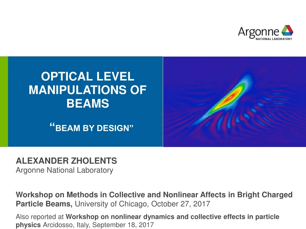
drhgfdjhngngfmhgmghmghjmghfmf Alexander Zholents Argonne National Laboratory Workshop on Methods in Collective and Nonlinear Affects in Bright Charged Particle Beams, University of Chicago, October 27, 2017 Also reported at Workshop on nonlinear dynamics and collective effects in particle physics Arcidosso, Italy, September 18, 2017 Optical level manipulations of beams “Beam by design”
Laser e-beam interaction in undulator Lu Undulator parameter Undulator/Modulator Electron motion in undulator
Laser e-beam interaction in undulator (cont’d) (plane wave approximation) Laser field kL=2p /lL laser wave vector Energy gain or loss by the electron FEL resonant energy where After averaging over the undulator period where PL is the laser peak power where P0 = 8.7 GW
Combination of One modulator and one magnetic chicane Coherent Harmonic Generation1 High Gain Harmonic Generation2 for A>>1 Ds p=DE/sE = Intensity modulation s/lL Bunching Jn is Bessel function of order n 1) Girard et al., 1984; Kinkaid et al., 1984 2) Ben-Zviet al., 1991; Yu et al., 1991; Allaria et al., 2013
Example: generation of attosecond x-ray pulses SASE FEL Current Enhanced Self Amplified Spontaneous Emission (ESASE)* current, (kA) electric field 10 mJ 1010ph one laser two lasers 250 asec t (fs) t (fs) Nearly Fourier transform limited x-ray pulse Carrier-envelop phase stabilized few cycle laser pulse *) Zholents, 2005; Zholentsand Penn, 2005; Y. Ding et al., 2009; Marinelli, 2016.
generation of attosecond x-ray pulses (cont’d) Tapered undulator method* Wigner transform of the on-axis far field Hard x-rays Soft x-rays lx=0.15 nm ~ 200 as Energy modulation Energy chirp is compensated by the undulator taper in the central slice Frequency chirp definition Wavelength, nm 7.6 Chirp x≈ 0.5 Contrast ≈ 1 7.7 7.8 Fourier transform limited pulse ~ 1.5 fs (FWHM) 7.9 -5 -2.5 0 2.5 t, fs W.M. Fawley, Nucl. Inst. and Meth. A 593, 111(2008). With two lasers one can manipulate the energy chirp and, thus, the frequency chirp *) E.L. Saldin, E.A. Schneidmiller, M.V. Yurkov, Phys. Rev. ST-AB 9, 050702 (2006).
Combination of two modulators and one magnetic chicane* Partial reduction of the energy spread induced by first modulator After second modulator Jia et al. After the chicane Energy spread histogram Bunching Favorable for HGHG *) McNeil et al., 2005; Allaria and De Ninno, 2007; Jia, 2008
Combination of two modulators and two magnetic chicanes* s/lL Echo Enabled Harmonic Generation (EEHG) 1 2 p 3 4 5 6 0.36 Efficient bunching Evolution of the longitudinal phase space through an EEHG system Intensity of COTR Only 1590 nm modulation, w1 experimental results Both 1590 nm and 795 nm modulations, w2 7th harmonic Radiation wavelength (nm) *) Stupakov, 2009; Xiang and Stupakov, 2009; Xiang et al., 2012; Zhao et al., 2012
Synthesis of radiation with an arbitrary waveform* Cascaded laser manipulations for tailoring the harmonic content of the radiation Quadrupoles are used in chicanes to control the sign of R56 Generation of odd-harmonic bunching for emission of square waveform fields p current Deleterious effects: • Incoherent synchrotron radiation • Intrabeam scattering • Coherent synchrotron radiation Bunching factor harmonic *) Hemsing and Xiang, 2013
Using TEM10 laser field mode Second order solution of paraxial wave equation can be used to impart an optical-scale angular kick to the electrons* y (1) TEM10 TEM10 -2 Gouy phase x energy modulation electron horizontal offset applying Panofsky-Wenzel theorem obtain angular modulation *) Zholents and Zolotorev, 2008
Application of angular modulation unwanted spikes Generation of a high-contrast attosecond x-ray pulses using a few-cycle laser pulse TEM00 TEM10 2 mm laser TEM00 2 mm laser TEM10 Due to transverse oscillations electrons acquire additional phase shift: LG is the FEL gain length kx =2p/lx is the x-ray wave number Slippage caused by transverse oscillations can increase or even “kill” the FEL gain
10-10 Px-ray (W) t (fs) Application of angular modulation (cont’d) Central peak Peak power Contrast > 100 (compare to ~ 1) 115 as, 10 mJ lx= 0.15 nm Peak power 100 GW
TM110 TM010 TM010 Deflecting cavity Application of angular modulation (cont’d) Emittance exchange (EEX) beamline with deflecting cavity* z → x and x → z emit. exch. QD QD QF QF B B QF QF QD QD B B B B QF QF QD QD Laser assisted EEX with angular modulation by the laser** B B CO2 *) Cornacchia and Emma, 2002; Emma et al., 2006; Sun et al., 2010; Xiang and Chao, 2011; Zholents and Zolotorev, 2011. **) Xiang, 2010
Application of angular modulation (cont’d) EEX for regular spaced clusters of electrons Initial x-x’ phase space x’(s) after interaction with laser High brightness electron clusters Final phase space x(s) after EEX Energy chirp before EEX and collimator after EEX can be used to select a single cluster Representative beam phase space evolution in EEX with a laser *) Xiang, 2010
Application of angular modulation (cont’d) Optical oscilloscope: combination of the rf deflector and laser deflector* (TEM10) mode Simulation: a fragment of the electron bunch on the YAG screen RF streaking Laser streaking *) Andonianet al., 2011
Laser heater* An effective tool to suppress microbunching instability The laser heater works by introducing a correlated microstructure in the phase space of the beam on the scale of the laser wavelength that is effectively washed out through transport, resulting in an increase in the uncorrelated energy spread. *) Saldin, Schneidmiller, Yurkov, 2004; Huang et al., 2004; Huang et al., 2010
Optical replica synthesizer* radiator, Bx modulator, By Polarizer FROG e- Evolution of the longitudinal phase space in a simplified ORS scheme FROG trace maps bunch shape: Electric field (a.u) t (fs) slice energy spread energy modulation *) Saldin et al., 2005; Salénet al., 2011;
Acknowledgement Many examples given in the presentation are taken from the paper: “Beam by design: Laser manipulation of electrons in modern accelerators” published in Rev. of Modern Phys., V. 86, p.897, (2014). And I benefited from many fruitful discussions with Erik Hemsing, Gennady Stupakov and Dao Xiang during the work on the paper.
Conclusion • Beam manipulations on the microscale, in particular those using the laser, have shown a tremendous potential for preparing the better beams • Many techniques have been adapted in practice and the number of newly proposed techniques continue to grow • The outlook for a future is very bright as new possibilities like transverse laser modulation and beam shaping are awaiting further explorations
BEAM CONDITIONING FOR FREE-ELECTRON LASERS* CONDITIONING MODIFYING BEAM PROPERTIES BY IMPOSING USEFUL CORRELATIONS ON A MICROSCALE *) Sessler, Whittum, Yu, Phys. Rev. Lett., 68, 309 (1992).
What “beam conditioning” does y y y z z z y y DE/E DE/E debunching happens no debunching Addresses the problem of de-bunching due to electron transverse oscillations in FEL microbunch undulator Solution of the problem: Providecorrelation between the amplitude of electron transverse oscillation and electron energy to speed up the electron Beam conditioning relaxes requirements on the beam emittance in FELs
e-beam !!! Laser-assisted electron beam conditioning* (extension of a time delay method proposed by Vinokurov) By utilizing laser and wiggler for electron energy modulation this scheme gives a factor of 105 better conditioning thanequivalent scheme based on RF cavities: *) Zholents, Phys. Rev. ST–Acc. and Beams, 8, 050701, (2005)
e-beam Laser-assisted electron beam conditioning cont’d Caution: approximately one half of electrons have wrong sign of correlations Best choice of parameters to achieve conditioning • short ~ 20 mm electron bunch, • single cycle 1.5 THz, ~15 mJlight pulse*) to chirp and de-chirp the electron bunch • one period wiggler *) feasible with the accelerator-based coherent emission THz source, i.e, like TeraFermi
Laser-assisted electron beam conditioning cont’d Example: LCLS-like FEL with ~5 times of LCLS emittance GENESIS simulations Beam parameters: energy = 14 GeV peak current = 3.4 kA, energy spread = 1.2 MeV, emittance = 2.4 mm-mrad, beta-function = 20 m. • - no conditioning, 2 - ideal conditioning (all electrons), 3 - partial conditioning.