Download
1 / 65
660 likes | 786 Views
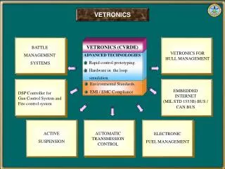
Matching Conducted EMI to International Standards. F. S. Dos Reis, J. C. M. de Lima, V. M. Canalli, J. A. Pomilio, J. Sebastián and J. Uceda. Table of Contents. ELECTROMAGNETIC COMPATIBILITY CONDUCTED EMI CONDUCTED EMI TEST SIMULATION FILTERING. INDUSTRIAL ENVIRONMENT.

E N D
Matching Conducted EMI to International Standards F. S. Dos Reis, J. C. M. de Lima, V. M. Canalli, J. A. Pomilio, J. Sebastián and J. Uceda 33 rd Power Electronics Specialists Conference
Table of Contents • ELECTROMAGNETIC COMPATIBILITY • CONDUCTED EMI • CONDUCTED EMI TEST • SIMULATION • FILTERING 33 rd Power Electronics Specialists Conference
INDUSTRIAL ENVIRONMENT 33 rd Power Electronics Specialists Conference
COMMUNICATIONENVIRONMENT 33 rd Power Electronics Specialists Conference
ALCA MERCOSUL European Union By Globalization´s Highway...International Rules... 33 rd Power Electronics Specialists Conference
By Globalization´s Highway...International Rules... Consumers RequirementsNo difference between domestic and commercial environment. In the last years...Technologic Advance 33 rd Power Electronics Specialists Conference
C cc CC - CC CONVENTIONAL INPUT RECTIFIER POWERLINE CAPACITORS VOLTAGE CC DIODES INPUT CURRENT POWERLINE CURRENT 33 rd Power Electronics Specialists Conference
CONVENTIONAL INPUT RECTIFIER * C:\MSIM60\EXAMPLES\EXAMPLE\RETCAP.SCH Date/Time run: 06/14/98 22:25:06 Temperature: 27.0 (L) C:\MSIM60\EXAMPLES\EXAMPLE\RETCAP.DAT 800 707 A CAPACITIVE FILTER RECTIFIER PURE RESISTIVE LOAD 400 307 A 50 A 0 -400 0s 10ms 20ms 30ms 40ms 50ms 60ms V(C1:2) -I(R2) V(D1:1,D4:2) -I(D2) I(D4) Time Date: June 14, 1998 Page 1 Time: 22:35:11 33 rd Power Electronics Specialists Conference
To solve those problems it was created the PFPs • Resistence Emulators. • Power Factor Corrector Preregulator. • Input Preregulator. • Power Factor Preregulator. 33 rd Power Electronics Specialists Conference
Objective Main Terms and Definitions Motivation Main Regulations about EMC EMC Limits Conducted EMI Conducted EMI Assays Techniques to Reduce EMI Conclusion INDEX 33 rd Power Electronics Specialists Conference
OBJECTIVES Means to determine, easily, the EMI levels, facing the following points: • Main Regulations; • Conducted EMI; • Conducted EMI Assays; • EMI Minimization Techniques. 33 rd Power Electronics Specialists Conference
MOTIVATION Power Quality: Noise Spoils the Power Quality. 33 rd Power Electronics Specialists Conference
MOTIVATION Examples of problems caused by EMI: • Drill Intervening on TV; • Electronic Ballast's makes the TV change the channel. • Switching Load noise in Radios. Necessity of accordance with Regulations. 33 rd Power Electronics Specialists Conference
TERMS AND DEFINITIONS Eletromagnetic Compatibility - EMC: • It´s the caracteristic presented by an equipment, or system, of operating, satisfactorily, in an electromagnetic environment without interfering or being interfered. 33 rd Power Electronics Specialists Conference
TERMS AND DEFINITIONS Electromagnetic Interference – EMI • It´s the spoiling on the performance of na equipment or system, caused by a electromagnetic disturb. 33 rd Power Electronics Specialists Conference
TERMS AND DEFINITIONS • IEC - International Electrotechnique Comission Comissão Eletrotécnica Internacional. • CISPR - International Special Committee on Radio Interference publication. • CENELEC - European committee to Electrotechinique Regulations 33 rd Power Electronics Specialists Conference
Basic Categories for EMC ELECTROMAGNETIC COMPATIBILITY EMISSION SUSCEPTIBILITY CONDUZIDA CONDUCTED IRRADIATED IRRADIATED ELECTROSTATIC POWER FLUTUATION HARMONICS RADIO-INTERFERENCE 33 rd Power Electronics Specialists Conference
MAIN REGULATIONS CISPR 14 • Engine operating equipment´s CISPR 16 • Disturbs and Immunity Methods and Measuring Equipment´s 33 rd Power Electronics Specialists Conference
EMC LIMITS Disturbs Level Immunity Limit Immunity Edge Immunity Edge Nível de compatibilidade Emission Edge Emission Limit Independent Variable 33 rd Power Electronics Specialists Conference
100 91 90 79 80 A and C Class 69.5 70 Limit Values 66 dB 60 60 57.5 µV 54 50 48 Class B 40 Limit Values 30 0.01 MHz 30 1 0.15 0.5 10 REGULATION LIMITS VDE 0871 33 rd Power Electronics Specialists Conference
CONDUCTED EMI It's the electromagnetic interference that propagates by power reliefs. This kind of interference can be: • Differential Mode (DM) • Commum Mode (CM) 33 rd Power Electronics Specialists Conference
CONDUCTED EMI IN DM F Z i red CMD Equipment N 33 rd Power Electronics Specialists Conference
CONDUCTED EMI IN CM? F Z i red CMC Equipment N 33 rd Power Electronics Specialists Conference
Interference Measurer Dipole Antenna EMI Receptor LISN I inter... U inter.. P 30 to 1000 MHz inter.. According to VDE 0871 e FCC 10 kHz to 30 MHz According to VDE 0871 450 kHz a 30 MHz H According to FCC 15 inter.. Interference supply Telescopic Antenna Loop Antenna E inter.. 10 kHz to 30 MHz Not Required by VDE According to VDE 0871 CONDUCTED EMI IN DM Line Impedance Stabilization Network 33 rd Power Electronics Specialists Conference
Open Field OATS Bigger Diameter = 2 X Smaller Diameter = 3 X X Antenna E U T 33 rd Power Electronics Specialists Conference
IRRADIATED EMI MEASURING PROCEEDINGS 33 rd Power Electronics Specialists Conference
ASSAYS DIFICULTIES Few able laboratories; High cost of the assays; Very expensive equipment; Technique capacitation; Regulations Interpretation; 33 rd Power Electronics Specialists Conference
CONDUCTED EMI ASSAYS F LISN Equipment Under Assay Measuring Instrument N 33 rd Power Electronics Specialists Conference
Condutive Surface Connected to Gnd EMI Receptor Under Assay Equipment 40 cm LISN 80 80 cm cm CONDUCTED EMI ASSAYS Available equipment´s under assay and measuring instruments 33 rd Power Electronics Specialists Conference
Condutive Surface Connected to Gnd EMI Receptor Under Assay Equipment 40 cm LISN 80 80 cm cm LISN CHARACTERISTICS CISPR 16 ± 20 % Maximum Tolerance ARTIFICIAL NETWORK Fre. Imp. kHz 10 5,4 Impedance 50µH 20 7,3 80 21 50 5 150 33 300 43 800 49 10000 50 Frequency (MHz) 33 rd Power Electronics Specialists Conference
COMERCIAL LISN 33 rd Power Electronics Specialists Conference
100 91 90 79 80 A and C Class 69.5 70 Limit Values 66 dB 60 60 57.5 µV 54 50 48 Class B 40 Limit Values 30 0.01 MHz 30 1 0.15 0.5 10 VDE 0871 33 rd Power Electronics Specialists Conference
If we realize that the equipment doesn’t follow the specification of a determined regulation... 33 rd Power Electronics Specialists Conference
HOW TO MINIMIZE THE EMI? Preventives: • Adjusted Control Methods (Tanaka, Wang, Albach, Lin, Willers, Simonetti) • Adjusted Topology (DosReis) • Adjusted Assembling Techniques 33 rd Power Electronics Specialists Conference
HOW TO MINIMIZE THE EMI? Correctives: Applying shielding. • Using Filter. 33 rd Power Electronics Specialists Conference
NETWORK FILTER EMI 33 rd Power Electronics Specialists Conference
Making Compatible Conducted EMI Generated for Power Factor Preregulators with the International Regulation 33 rd Power Electronics Specialists Conference
SOLUTIONS AVAILABLE CURRENTLY • Input Current. • LISN • EMI Receptor. Quantify EMI 33 rd Power Electronics Specialists Conference
Objectives Quantify EMI ( abacuses ). Minimize EMI ( FM and filter). $ 33 rd Power Electronics Specialists Conference
Why the Variable Frequency Techniques reduce EMI? 33 rd Power Electronics Specialists Conference
Given an usual Input Current Harmonic Spectrum f. Constant. 10 1000 kHz 33 rd Power Electronics Specialists Conference
Given an usual Input Current Harmonic Spectrum f. Variable. 10 1000 kHz 33 rd Power Electronics Specialists Conference
FM xF constant 33 rd Power Electronics Specialists Conference
MEASURING SYSTEM LISN Filter + I (t) g L int U (t) int R 2 R 1 - Demodulator Quase-Peak Measurer + + + + R D R D 1D 1w C U (t) U (t) U (t) U (t) D int CD R C D w R 2D 2w w - - - - 33 rd Power Electronics Specialists Conference
EMI RECEPTOR CHARACTERISTIC 33 rd Power Electronics Specialists Conference
+ i i - D g d Q C i ( t) cc + g v R v L g e - t 1 :n + T V - PFP WITH BUCK-BOOST CONVERTER 33 rd Power Electronics Specialists Conference
+ + i L g C 2 Q i ( t) g C R + cc V v L v g 1 e D - i d t 1 :n T - - PFP WITH ZETA CONVERTER 33 rd Power Electronics Specialists Conference
PFP WITH BOOST CONVERTER i i g d + + L D + i ( t) g v ( t) C i g V cc v R g med e - t - - 33 rd Power Electronics Specialists Conference
i ( t) g i ( t) g med t PFP WITH SEPIC CONVERTER L D C 1 i g + + i d R + Q V v L v g 2 C e cc - 1 :n T - - 33 rd Power Electronics Specialists Conference
EMI FILTER EFFECT dB µV Frecuencia de operación del convertidor (MHz) 33 rd Power Electronics Specialists Conference