Download
1 / 18
180 likes | 297 Views
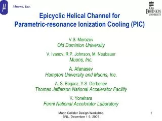
Epicyclic Helical Channels for Parametric-resonance Ionization Cooling. Andrei Afanasev , Hampton U/ Muons , Inc Yaroslav Derbenev , JLab Rolland P. Johnson, Muons , Inc Valentin Ivanov , Muons , Inc + Muons , Inc collaborators.

E N D
Epicyclic Helical Channels for Parametric-resonance Ionization Cooling Andrei Afanasev, Hampton U/Muons, Inc YaroslavDerbenev, JLab Rolland P. Johnson, Muons, Inc ValentinIvanov, Muons, Inc +Muons, Inc collaborators
Generating Variable DispersionModified Helical Solenoid • This is a demo of a beamline that satisfies conditions for alternating dispersion function needed for Parametric-resonance Ionization Cooling (PIC) • Detailed simulations for the proposed beamline are in progress
PIC Concept • Muon beam ionization cooling is a key element in designing next-generation high-luminosity muon colliders • To reach high luminosity without excessively large muon intensities, it was proposed to combine ionization cooling with techniques using parametric resonance (Derbenev, Johnson, COOL2005 presentation) • A half-integer resonance is induced such that normal elliptical motion of x-x’ phase space becomes hyperbolic, with particles moving to smaller x and larger x’ at the channel focal points • Thin absorbers placed at the focal points of the channel then cool the angular divergence of the beam by the usual ionization cooling mechanism where each absorber is followed by RF cavities
PIC Concept (cont.) Absorber plates Parametric resonance lenses Comparison of particle motion at periodic locations along the beam trajectory in transverse phase space Ordinary oscilations vs Parametric resonance Conceptual diagram of a beam cooling channel in which hyperbolic trajectories are generated in transverse phase space by perturbing the beam at the betatron frequency
PIC Challenges • Large beam sizes, angles, fringe field effects • Need to compensate for chromatic and spherical aberrations • Requires the regions with largedispersion • Absorbers for ionization cooling have to be located in the region of smalldispersion to to reduce straggling impact • Suggested solution (Derbenev, LEMC08; AA, Derbenev, Johnson, EPAC08): Design of a cooling channel characterized by alternating dispersion and stability provided by a (modified) magnetic field of a solenoid; avoid fringe fields by introducing a continuous periodic helical-type structure
Helical Cooling Channel (HCC) • Proposed to use for 6D muon cooling with homogeneous absorber, see for details Derbenev, Johnson, Phys.Rev.ST Accel.Beams 8, 041002 (2005) • Under development by Muons, Inc. • Y. Derbenev and R. Johnson, Advances in Parametric Resonance Ionization Cooling, ID: 3151 - WEPP149, EPAC08 Proceedings • V. Kashikhin et al., Design Studies of Magnet Systems for Muon Helical Cooling Channels, ID: 3138 - WEPD015, EPAC08 Proceedings
Helical Solenoid Helical Solenoid geometry and flux density for the Helical Solenoid magnet
Straight (not helical) Solenoid • Bz=B0, Bx=By=0 • Dispersion= 0 XY-plane
Helical Solenoid • Derbenev, Johnson, Phys.Rev.ST Accel.Beams 8, 041002 (2005) • Dispersion= const • Orbit is constrained by a ring (adiabatic case) • Periodic orbit is a circle for a particular choice of initial conditions(non-adiabatic case) XY-plane
Our Proposal:Epicyclic Helical Solenoid • Superimposed transverse magnetic fields with two spatial periods • Variable dispersion function XY-plane k1=-2k2 B1=2B2 EXAMPLE
EpicyclicHelicalSolenoid (cont.) • Wave numbers k1,k2 may be opposite-sign or same-sign • Beam contained (in the adiabatic limit) by • Epitrochoid (same sign) - planet’s trajectory in Ptolemy’s system • Hypotrochoid (opposite-sign)- special case is an ellipse k1=2k2 B1=2B2 k1=-k2 B1=2B2 k1=-2k2 B1=2B2
Particle Trajectory in Solenoid+Double-Periodic Transverse Field In the adiabatic limit k1=-k2<<kc transverse-plane trajectory is bound by an ellipse
Periodic Orbits in EHS , . • Equation of motion • b1, b2 - transverse helical fields with spatial periods described by wave-number parameters k1 and k2, • Cyclotron wave number • Approximation pz=const gives analytic solution for eqs. of motion .
Oscillating Dispersion . • The dispersion function for such an orbit is a superposition of two oscillating terms, • The dispersion function has nodes if • For example, k1=-k2=kc/2, then B2=9B1 , solution for the orbit is • Dispersion function is periodic and sign-changing • Numerical analysis with Mathematica (with no pz=const approximation) gives close results
Transverse-plane Trajectory in EHS B1≠0, B2=0 (HS) → B1≠0, B2≠0 (EpicyclicHS) p→p+Δp k1=-k2=kc/2 k1=-k2/2=kc/4 • Change of momentum from nominal shows regions of zero dispersion • and maximum dispersion • Zero dispersion points: Locations of plates for ionization cooling • Maximum dispersion: Correction for aberrations
Periodic orbit in Epicyclic HS • Conditions for the periodic orbit need to be satisfied HS Epicyclic HS -Derbenev, Johnson, PRST (2005) Numerical analysis (using Mathematica for tracking): Transverse-plane periodic orbit is elliptic at low kappa (~0.1-0.2), but deviates from ellipse at large kappa (>1)
Designing Epicyclic Helical Channel • Solenoid+direct superposition of transverse helical fields, each having a selected spatial period • Or modify procedure by V. Kashikhin and collaborators for single-periodic HCC [V. Kashikhin et al., Design Studies of Magnet Systems for Muon Helical Cooling Channels, ID: 3138 - WEPD015, EPAC08 Proceedings • Magnetic field provided by a sequence of parallel circular current loops with centers located on a helix • (Epicyclic) modification: Circular current loops are centered along the epitrochoids or hypotrochoids. The simplest case will be an ellipse (in transverse plane) • Detailed simulations are needed
Implementing in PIC • Plan to develop an epicyclic helical solenoid as part of PIC cooling scheme and Reverse-Emittance Exchange • Elliptic option looks the simplest • Detailed theory, numerical analysis and simulations are in progress • V. Ivanov, G4BL simulations +Muons, Inc collaborators