Download
1 / 29
290 likes | 498 Views
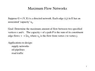
Flow Networks. Topics Flow Networks Residual networks Ford-Fulkerson’s algorithm Ford-Fulkerson's Max-flow Min-cut Algorithm. Chapter 7 Algorithm Design Kleinberg and Tardos. Flow Networks. A directed graph can be interpreted as a flow network to analyse material flows through networks.

E N D
Flow Networks Topics Flow Networks Residual networks Ford-Fulkerson’s algorithm Ford-Fulkerson's Max-flow Min-cut Algorithm Chapter 7 Algorithm Design Kleinberg and Tardos CSE 5311 Kumar
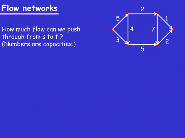
Flow Networks • A directed graph can be interpreted as a flow network to analyse material flows through networks. • Material courses through a system from a source (where it is produced) to a sink (where it is consumed). • Examples : • Water through pipelines • Newspapers through distribution system • Electricity through cables • Cars on a production line • on roads • The source produces the material at a steady rate . • The sink consumes the material at a steady rate CSE 5311 Kumar
Flow: the rate at which the material moves from one point to another 100 litres of water per hour in a pipe 30 Amperes of electric current in a circuit 25 litres/hour 5 litres/hour 30 liters/hour The rate at which a material enters a vertex = the rate at which the material leaves the vertex CSE 5311 Kumar
The flow network G =(V,E) is a directed graph in which each edge (u,v) E has a nonnegative capacity c(u,v) 0. If (u,v) E then c(u,v) = 0. A flow network has a source vertex s, and a sink vertex t. For every vertex v V there is a path from s to v and v to t in a connected graph. s t source sink CSE 5311 Kumar
A flow in G is a real-valued function f : V V R that satisfies the following three properties: 1. Capacity constraint : For all u,v V, we require f(u,v)c(u,v). The net flow from one vertex to another must not exceed the given capacity. 2. Skew symmetry : For all u,v V, we require f(u,v) = -f(v,u). The net flow from a vertex u to a vertex v is the negative of the net flow in the reverse direction. The net flow from a vertex to itself is zero for all uV, that is f(u,u) = 0. 3. Flow conservation : For all u V - {s,t}, we require The total net flow out of a vertex other than the source or sink is zero. CSE 5311 Kumar
The quantity f(u,v) can be negative or positive, it is called the net flow from vertex u to v. The value of a flow is defined as In the maximum-flow problem, we are given a flow network G with source s and sink t, and we wish to find a flow of maximum value from s to t. There is no net flow between u and v if there is no edge between them. If (u,v) E and (v,u) E, then c(u,v) = c(v,u) = 0. Hence, the capacity constraint, f(u,v) 0 and f(v,u) 0. By skew symmetry, f(u,v) = -f(v,u), therefore, f(u,v) + f(v,u) = 0. Nonzero net flow from vertex u to vertex v implies that (u,v)E or (v,u)E (or both). CSE 5311 Kumar
Consider the network G=(V,E) shown in the figure below. The network is for a transport system that transports crates of an item from source vertex s to sink vertex t through a number of intermediate points. Each edge (u,v) E in the network is labeled with its capacity c(u,v). c a 12 20 16 4 9 7 10 s t 13 4 14 d b CSE 5311 Kumar
Let us consider a flow in G, f=19 If f(u,v) >0, edge (u,v) is labeled f(u,v)/c(u,v) If f(u,v) 0, the edge is labeled by its capacity only. c a 12/12 15/20 11/16 1/4 7/7 4/9 s t 10 8/13 4/4 11/14 d b CSE 5311 Kumar
a a a 3/8 8 5/8 2/3 3 3 b b b Fig.a Fig.c Fig.b The positive net flow entering a vertex v is defined by Initially, c (a ,b) = 8, and c (b, a) = 3 -- Fig. a. f (a, b) = 5 and f (b, a) = 2, -- Fig. b the net flow is shown as 3/8 in direction a to b – Fig. c CSE 5311 Kumar
a a a a 3/8 8 5/8 8 2/3 3 3 1/3 b b b b Fig.c Fig.b Fig.d Fig.a If we increase the flow from b to a from 2 to 6 then the net flow is 1/3 in the direction b to a as shown in Fig. d. CSE 5311 Kumar
The Ford_Fulkerson method • The method is iterative, • Starts with f(u,v) for (u,v)V, initial flow of value 0. • The method is based on the augmenting path which is defined as a path from s to t along which we can push more flow and then augment flow along this path. • Procedure Ford_Fulkerson_method(G,s,t) • 1. f 0; • 2. while there exists an augmenting path p • 3.do augment flow along path p • 4. return f CSE 5311 Kumar
Residual Networks • Consider a flow network G(V,E) with source s and sink t and let f be a flow in G. • Consider a pair of vertices u,v V. • Residual capacity between u and v is given by • r(u,v) = c(u,v) - f(u,v) • the additional net flow we can push from u to v before exceeding the capacity. For example, if c(u,v) = 25 and f(u,v) = 19, then r(u,v) = 6. • If f(u,v) < 0 then r(u,v) > c(u,v) • Given a flow network G=(V,E) and a flow f, the residual network of G induced by f is Gf=(V,Ef), • where Ef ={(u,v) V V : r(u,v) > 0} CSE 5311 Kumar
c c a a 12/12 12 15/20 5 11/16 5 1/4 5 7/7 4/9 s t 3 15 11 10 7 s t 4 8/13 4/4 5 11 4 4 11/14 8 d b 3 d b 11 Each edge in the residual network can admit positive net flow only. The residual network may include several edges that are not in the original network, (u,v) Ef and (u,v) E is possible (Ef is not a subset of E). However, (u,v) appears in Gfonly if (v,u) E and there is a positive flow from v to u. Because the net flow f(u,v) is negative, r(u,v) = c(u,v)-f(u,v) > 0 and (u,v)Ef CSE 5311 Kumar
An edge (u,v) can appear in a residual network only if at least one of (u,v) and (v,u) appears in the original network. Ef 2E Augmenting Paths It is a simple path from s to t in Gf. Each edge (u,v) on an augmenting path admits some additional positive net flow from u to v without violating the capacity constraint on the edge. The residual capacity of a path p is given by, r(p) = min { r(u,v) : (u,v) is in p } CSE 5311 Kumar
Let's define a flow function fp, fp is a flow in Gf with value fp= r(p) >0. If we add fp to f, we get another flow in G whose value is closer to the maximum. CSE 5311 Kumar
Algorithm • Procedure Ford-Fulkerson(G,s,t) • Input : Flow Network G(V,E) • Output : Maximum flow for the given network • 1.for each edge (u,v) E • 2. do f[u,v] 0; • 3.f[v,u] 0; • 4.while there exists a path p from s to t in the residual network Gf • 5. do r(p) min {r(u,v) : (u,v) is in p}; • 6. for each edge (u,v) in p • 7. do f[v,u] - f[u,v]; • 8.f[u,v] f[u,v] + r(p); • 9.return CSE 5311 Kumar
c a 12 20 16 4 9 7 10 s t 13 4 14 d b c a 4/12 20 4/16 4 7 4/9 s t 10 4/4 13 4/14 d b CSE 5311 Kumar
c a 8 20 4 12 4 4 7 4 s 5 t 10 13 4 10 d b 4 c a 4/12 20 c a 4/12 4/16 7/20 11/16 4 7 4/9 s t 4 7/7 10 4/9 s t 7/10 4/4 13 4/4 13 4/14 d b 11/14 d b CSE 5311 Kumar
c a 8 13 4 5 11 4 7 11 7 s 5 t 3 13 4 3 d b 11 c c a a 4/12 12/12 7/20 15/20 11/16 11/16 4 1/4 7/7 7/7 4/9 4/9 s s t t 10 7/10 4/4 4/4 8/13 13 11/14 11/14 d b d b CSE 5311 Kumar
c a 5 5 12 11 11 4 7 15 s 5 t 3 8 5 4 3 d b 11 c a 12/12 19/20 11/16 1/4 7/7 4/9 s t 10 4/4 12/13 11/14 d b c a 12/12 15/20 11/16 1/4 7/7 4/9 s t 10 4/4 8/13 11/14 d b CSE 5311 Kumar
c a 12/12 19/20 11/16 1/4 7/7 4/9 s t 10 4/4 12/13 c a 11/14 d b 5 1 12 11 11 7 19 s 9 t 3 12 1 4 3 d b 11 CSE 5311 Kumar
Complexity of the algorithm • Number of iterations of the while loop • All capacities are integers • Amount of work in each iteration of the while loop • Number of edges in the graph CSE 5311 Kumar
12/12 v3 v1 11/16 19/20 10 1/4 7/7 S t 0/9 4/4 12/13 v2 v4 11/14 f (S, T) = f (u, v) u S v T S T Minimum Cuts Cut (S,T) of a flow network A cut (S,T) of a flow network G=(V,E) is a partition of V in to S and T = V \ S such that s S and t T. In the example: S = {s,v1,v2), T = {v3,v4,t} Net flow f (S ,T) = f (v1,v3) + f (v2,v4) + f (v2,v3) = 12 + 11 + (-0) = 23 Capacity c(S,T) = c(v1,v3) + c(v2,v4) = 12 + 14 = 26 CSE 5311 Kumar
Ford Fulkerson – cuts of flow networks Assumption: The value of any flow f in a flow network G is bounded from above by the capacity of any cut of G Lemma: | f | <c (S, T) 12/12 | f | = f (S, T) = f (u, v) < c (u, v) = c (S, T) v3 v1 11/16 19/20 10 1/4 7/7 S t 0/9 u S v T 4/4 u S v T 12/13 v2 v4 11/14 CSE 5311 Kumar
Suppose that each source si in a multisource, multisink problem produces exactly piunits of flow, so that f(si,V) = pi. Suppose that each sink tjconsumes exactly qj units so that f(V,tj) = qj, where . Show how to convert the problem of finding a flow f that obeys these additional constraints into the problem of finding a maximum flow in a single-source, single-sink flow network. • Given a flow network G = (V, E), let f1 and f2 be functions from VV to R. The flow sum f1 + f2 is the function from VV to R defined by (f1 + f2)(u, v) = f1(u, v) + f2(u, v) for all u, vV. If f1 and f2 are flows in G, which of the three flow properties must the flow f1 + f2 satisfy, and which might it violate? • The edge connectivity of an undirected graph is the minimum number k of edges that muct be removed to disconnect the graph. For example, the edge connectivity of a tree is 1, and the edge connectivity of a cyclic chain of vertices is 2. Show that how the edge connectivity of an undirected graph G = (V,E) can be determined by running a maximum-flow algorithm on at most Vflow networks, each having O(V) vertices and O(E) edges. CSE 5311 Kumar
Bipartite Matching • Finding a matching M in G of largest size • A bipartite graph G = (V,E) is an undirected graph whose node set is partitioned into two sets X and Y such that V = XY. Every edge e E has one end in X and the other end in Y. • A matching M in G is a subset of the edges M E such that each node v V appears in at most one edge in M. CSE 5311 Kumar
s t Bipartite graph and Flow Network u v Each edge has a capacity of ONE CSE 5311 Kumar
s t s t s t s t s t v1-u1 v2-u3 v3-u5 v5-u4 s t CSE 5311 Kumar