Download
1 / 47
490 likes | 629 Views
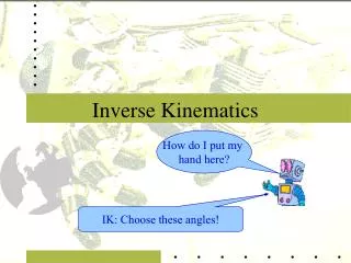
Inverse Kinematics –IKS Solutions. ME 4135 – Robotics and Controls R.R. Lindeke, Ph.D., Fall 2011. FKS vs. IKS. In FKS we built a tool for finding end frame geometry from Given Joint data: In IKS we need Joint models from given End Point POSE Geometry :. Cartesian Space. Joint Space.

E N D
Inverse Kinematics –IKS Solutions ME 4135 – Robotics and Controls R.R. Lindeke, Ph.D., Fall 2011
FKS vs. IKS • In FKS we built a tool for finding end frame geometry from Given Joint data: • In IKS we need Joint models from given End Point POSE Geometry: Cartesian Space Joint Space Joint Space Cartesian Space
So this IKS is ‘Nasty’ – it is a so-call Hard Mathematical Problem • It a more difficult problem because: • The Equation set is “Over-Specified” • 12 equations in 6 unknowns • Space may be “Under-Specified” • for example ‘Planer devices’ with more joints than 2 • The Solution set can contain Redundancies • Thus they exhibit Multiple solutions • The Solution Sets may be un-defined • Unreachable in 1 or many joints
But the IKS in Critical in Robotics • Builds Workspace limits and controller maps • Allows “Off-Line Programming” solutions • Thus, compares Workspace capabilities with Programming desirability to assure that execution is feasible • Aids in Workplace design and operational simulations
Doing a Pure IKS solution: the R Manipulator R Frame Skeleton
Forming The IKS: • Examining the two sides of this FKS equation • n, s, a and d are given in an inverse sense – since we desire to put the manipulator on a particular target • But we will build the general solution only • Term (1, 4) & (2,4) both side allow us to find an equation for : • Select (1,4): C1*(d2+cl2) = dx • Select (2,4): S1*(d2+cl2) = dy • Form a ratio of Term2,4 by Term1,4 to build an equation for Tan() and then : • S1/C1 = dy/ dx • Tan = dy/dx • = Atan2(dx, dy)
Forming The IKS: • After is found, back substitute and solve for d2: • Choose term(1,4): C1*(d2+cl2) = dx • Isolating d2: d2 = [dx/C1] - cl2
Alternative Method – doing a pure inverse approach • Form [A1]-1then pre-multiply both side by this ‘inverse’ • Leads to: A2 = A1-1*T0ngiven
Solving: • Selecting and Equating terms (1,4) • 0 = -S1*dx + C1*dy • Solving: S1*dx = C1*dy • Tan() = (S1/C1) = (dy/dx) • = Atan2(dx, dy) • Selecting and Equating terms (3,4) -- after back substituting solution – and note, after the above step, is known as an angle • d2 + cl2 = C1*dx + S1*dy • d2 = C1*dx + S1*dy- cl2 d2 = Cos[Atan2(dx, dy)]*dx + Sin[Atan2(dx, dy)]*dy –cl2
Performing IKS For Industrial Robots: • First lets consider the previously defined Spherical Wrist simplification • All Wrist joint Z’s intersect at a point • The n Frame is offset from this intersection as a distance dn along the a vector of the desired solution (3rd column of desired orientation sub-matrix) • This is as expected by the DH Algorithm
Performing IKS • We can now separate the effects of the ARM joints • Joints 1 to 3 in a full function manipulator (without redundant joints) • They function to position the spherical wrist at a target POSITION related to the desired target POSE • Arm Joints are separated from the WRIST Joints • Joints 4 to 6 in a full functioning spherical wrist • Wrist Joints function as a primary tool to ORIENT the end frame as required by the desired target POSE
Performing IKS: Focus on Positioning • We will define a point (the WRIST CENTER) as: • Pc = [Px, Py, Pz] • Here we define Pc = dtarget - dn*a • Px = dtarget,x - dn*ax • Py = dtarget,y - dn*ay • Pz = dtarget,z - dn*az
Focusing on the ARM Manipulators in terms of Pc: • Prismatic: • q1 = Pz (its along Z0!) – cl1 • q2 = Px or Py - cl2 • q3 = Py or Px - cl3 • Cylindrical: • 1 = Atan2(Px, Py) • d2 = Pz – cl2 • d3 = Px*C1 – cl3 or +(Px2 + Py2).5 – cl3
Focusing on the ARM Manipulators in terms of Pc: • Spherical: • 1 = Atan2(Px, Py) • 2 = Atan2( (Px2 + Py2).5 , Pz) • D3 = (Px2 + Py2 + Pz2).5 – cl3
Focusing on the ARM Manipulators in terms of Pc: • Articulating: • 1 = Atan2(Px, Py) • 3 = Atan2(D, (1 – D2).5) • Where D = • 2 = - • is: Atan2((Px2 + Py2).5, Pz) • is:
One Further Complication: • This is called the d2 offset problem • A d2 offset is a problem that states that the n frame has a non-zero offset along the Y0 axis as observed with all joints at home, in the solution of the 0Tn • This leads to two solutions for 1 the So-Called Shoulder Left and Shoulder Right solutions
Defining the d2 Offset issue Here: ‘The ARM’ might be a prismatic joint as in the Stanford Arm or it might be l2& l3links in an Articulating Arm and rotates out of plane A d2 offset means that there are two places where 1 can be placed to touch a given point (and note, when 1is at Home, the wrist center is not on the X0 axis!)
Lets look at this Device “From the Top” L3’ L2’ X1 11
Solving For 1 • We will have a Choice (of two) poses for :
In this so-called “Hard Arm” • We have two 1’s • These lead to two 2’s (Spherical) • Or to four 2’s and 3’s in the Articulating Arm • Shoulder Right Elbow Up & Down • Shoulder Left Elbow Up & Down
The Orientation Model • Evolves from: • Separates Arm Joint and Wrist Joint Contribution to Target (given) orientation
Focusing on Orientation Issues • Lets begin by considering Euler Angles (they are a model that is almost identical to a full functioning Spherical Wrist): • Form Product: • Rz1*Ry2*Rz3 • This becomesR36
Euler Wrist Simplified: And this matrix is equal to a U matrix prepared by multiplying the inverse of the ARM joint orientation matrices inverse and the Desired (given) target orientation NOTE: R03 is Manipulator dependent!
Solving for Individual Orientation Angles (1st): • Selecting (3,3)→ C= U33 • With Cwe “know” S= (1-C2).5 • Hence: = Atan2(U33, (1-U332).5 • NOTE: 2 solution for !
Re-examining the Matrices: • To solve for : Select terms: (1,3) & (2,3) • CS = U13 • SS = U23 • Dividing the 2nd by the 1st: S /C = U23/U13 • so Tan() = U23/U13 • leading to: = Atan2(U13, U23)
Continuing our Solution: • To solve for : Select terms: (3,1) & (3,2) • -SC = U31 • SS = U32 • so Tan() = U32/-U31 (note the ‘minus’ sign track the appropriate term!) • And Thus = Atan2(-U31, U32)
Summarizing: • = Atan2(U33, (1-U332).5 • = Atan2(U13, U23) • = Atan2(-U31, U32)
Solving: • After Examination here let’s select (3,3) both sides: • 0 = C4U23 – S4U13 • S4U13 = C4U23 • Tan(4) = S4/C4 = U23/U13 • 4 = Atan2(U13, U23) • With the given and back-substituted values (from the arm joints) we have a value for 4 the RHS is completely known
Solving for 5 & 6 • For 5: Select (1,3) & (2,3) terms • S5 = C4U13 + S4U23 • C5 = U33 • Tan(5) = S5/C5 = (C4U13 + S4U23)/U33 • 5 = Atan2(U33, C4U13 + S4U23) • For 6: Select (3,1) & (3, 2) • S6 = C4U21 – S4U11 • C6 = C4U22 – S4U12 • Tan(6) = S6/C6 = ([C4U21 – S4U11],[C4U22 – S4U12]) • 6 = Atan2 ([C4U21 – S4U11], [C4U22 – S4U12])
Summarizing: • 4 = Atan2(U13, U23) • 5 = Atan2(U33, C4U13 + S4U23) • 6 = Atan2 ([C4U21 – S4U11], [C4U22 – S4U12])
Lets Try One: • Cylindrical Robot w/ Spherical Wrist • Given a Target matrix (it’s an IKS after all!) • The d3 “constant” is 400mm; the d6 offset (call it the ‘Hand Span’) is 150 mm. • 1 = Atan2((dx – ax*150),(dy-ay*150)) • d2 = (dz – az*150) • d3 = ((dx – ax*150)2,(dy-ay*150)2).5 - 400
The Frame Skeleton: Note “Dummy” Frame to account for Orientation problem with Spherical Wrist
Solving for U: NOTE: We needed a “Dummy Frame” to account for the Orientation issue at the end of the Arm
Subbing Uij’s Into Spherical Wrist Joint Models: • 4 = Atan2(U13, U23)= Atan2((C1ax + S1az), (S1ax-C1az)) • 5 = Atan2(U33, C4U13 + S4U23)= Atan2{ay, [C4(C1ax+S1az) + S4 (S1ax-C1az)]} • 6 = Atan2 ([C4U21 - S4U11], [C4U22 - S4U12]) = Atan2{[C4(S1nx-C1nz) - S4(C1nx+S1nz)], [C4(S1sx-C1sz) - S4(C1sx+S1sz)]}