Download
1 / 13
130 likes | 228 Views
Burn-in Viewer User ’s Guide Version 2.0 February 17, 2005 LukasTomasek < tomasekl@fzu.cz >. 1. Start binBurnInViewer.exe. You should see this panel:. 2. Select valid files and directories

E N D
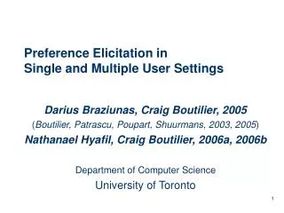
Burn-in Viewer User’s Guide Version 2.0February 17, 2005LukasTomasek <tomasekl@fzu.cz>
1. Start bin\BurnInViewer.exe. You should see this panel: 2. Select valid files and directories The last settings is automatically saved (config.cfg) and loaded after the next startup. Edit general config. options. This settings is common to all modules and not saved to config file. (Is there any need for different TDAQ Set for each module??)
3. Go to Module Detail tab and edit the user limits (watch points). If any of these values will be exceeded, you will be notified. The shown limits are valid only for the module (channel) selected in Module Status panel. Each module can have different limits. You can apply the same limits to all modules using Apply to All button. Set as Default button saves the limits to a file (limits.cfg). The default settings is loaded after startup and can be reloaded using Load Default button. The desired limits can be changed anytime. NOTE: Changed values are not valid until you press Enter!!
4. Turning this button ON starts periodic readout of the data log files with desired period. (Stop by turning OFF) Module Status panel and the detail for selected module is updated each cycle. If the update canvas check box is selected, root canvas is also redrawn every period automatically (see warning at the bottom of the page). Update Canvas button reads the current data and updates the canvas(independently on the automatic update). The progress bar displays completed fraction of the test (Last-Connected)/total, where the total burn-in time length is selected in Config panel. If any user limit is exceeded, the Module Status button is red. Yellow is low voltage off (both VDD and VDA), blue both on & IDA=0, green with IDA>0 (module configured), violet only one turned on. Click on the button to see the module detail below. The DAQ status is indicated separately by small “LED” next to module button (green – ok, red – error). Module Detail status shows min, max and last value. The red background means that limit was exceeded (any recorded value, not only the last one!). Here can be selected the interval of interest for the plots. Last&min& max is also valid only on this interval. The starting time can be reset to the current time using the button or directly edited (don’t forget to hit Enter). Red background if chamber temp limits exceeded. WARNING: There is a memory leak in the routine updating the Root Canvas in this version of the Viewer. So don‘t leave canvas update check box selected when it‘s not necessary (overnight etc.). Just hit Update Canvas Button when you need to redraw the canvas instead. The periodic data update without canvas is safe.
You can also edit the last time of interest by clicking this check box. However this feature is meant mainly for the offline processing when the update button is OFF (otherwise is disabled during each automatic update). The Print button next to DAQ limits prints out a simple summary of the digital and analog scans for selected module on selected time interval. (only for files already processed by Viewer!!). DAQ status is updated only when the periodic readout is ON. The HV OFF scans are distinguished by file name (must contain HVOFF string).
5. Root Canvas You can use all standard features of the Root graphs and canvases (zooming, printing etc..).
6. Log Message In case of any ”predicted“ program error or warning (file not found …) a log message is generated. When this happens, the Log Message window will appear in front. Each message is also appended to BurnInViewer.log file that can be found in the same directory as the BurnInViewer.exe .
7. Module Analysis Panel Summary ROOT files readable by Module Analysis Framework can be generated from this panel. Select desired input options (TDAQ status and set is selected in Config panel!) and hit Generate Root Files button. For each module from the current burn-in configuration (defined in module.table) two Root files are generated. The *.root one contains all V,I,T data and also data from all TDAQ scans (standard MAF sets, histos & log). The second one (*_summary.root ) only the V,I,T data and a summary of the scans (threshold&noise for each threshold scan and number of bad pixels for a digital scan). Both are saved in the TDAQStatus+Set directory. After the Root files have been generated only the summaries are automatically loaded into the “built-in” Module Analysis Framework Panel. Web upload is in debug. stage yet…
8. Module Analysis Framework example Here is an example of the ”full” Root file loaded in MAF. Scan labels with the detail information (NTC, threshold, time stamp etc.) are generated only when you hit Plot scan summary.
MAF burn-in summary plots: • Plot summary of scans NumFits – number of pixels with good fit (out of 46080); Bad Pixels – number of pixels from a digital injection scan with incorrect number of hits; FE Errors – sum of all FE errors from log file,, MCC Errors – sum of all MCC errors except 0/1 errors, MCC “01“ Errors – only MCC 0/1 errors.
Plot V, I, T vs Time • MAF expects these default log files in the /data/ambush directory - chtemp.log, temp.log, • volta.log, curra.log, voltd.log, currd.log, hv.log, hi.log . More details in AMBuSh documentation. Bias V,I vs time (if data available)
Plot V,I vs NTC Bias current vs NTC (if data available)
Some notes… • Please, check that the time of scans in the Root graphs matches the times • from log files and the NTC temperature attached to it is correct. If they are • accidentally shifted by 1 hour, let me know. • The current algorithm used to generate the root files requires a lot of memory, since • it loads all the scans for a module to MAF first and then generates the summary. • Also has some memory leaks, so it’s recommended to close the Viewer after • the summary root files have been generated. • To do… • Improve memory management (esp. root files generation, graphs) – Viewer&MAF, • Debug and complete Web upload. • Fix Root warnings (Linux version). • Any suggestions?? (tomasekl@fzu.cz)