Download
1 / 28
280 likes | 386 Views
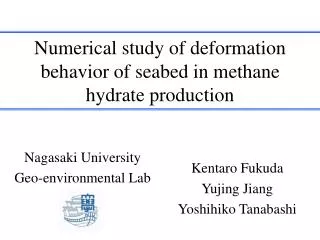
Numerical study of the thermal behavior of an Nb 3 Sn high field magnet in He II. Slawomir PIETROWICZ, Bertrand BAUDOUY CEA Saclay Irfu , SACM 91191 Gif- sur -Yvette Cedex , France s lawomir.pietrowicz@cea.fr. CHATS on Applied Superconductivity (CHATS-AS ), October 12-14 2011, CERN.

E N D
Numerical study of the thermal behavior of an Nb3Sn high field magnet in He II Slawomir PIETROWICZ, Bertrand BAUDOUY CEA Saclay Irfu, SACM 91191 Gif-sur-Yvette Cedex, France slawomir.pietrowicz@cea.fr CHATS on Applied Superconductivity (CHATS-AS), October 12-14 2011, CERN
Outline • Motivation • Two – fluid model • Simplified model of He II • Validation of simplified model Steady state modeling • Modeling of thermal – flow process during AC losses in Nb3Sn magnet – steady state • Description of Fresca II magnet; • 3D computational region, assumption and boundary conditions; • Mesh; • Numerical results. Unsteady state modeling • Modeling of thermal process during quench heating – unsteady state model • Geometry and mesh; • Numerical results. • Conclusions
Outline • Motivation • Two – fluid model • Simplified model of He II • Validation of simplified model Steady state modeling • Modeling of thermal – flow process during AC losses in Nb3Sn magnet – steady state • Description of Fresca II magnet; • 3D computational region, assumption and boundary conditions; • Mesh; • Numerical results. Unsteady state modeling • Modeling of thermal process during quench heating – unsteady state model • Geometry and mesh; • Numerical results. • Conclusions
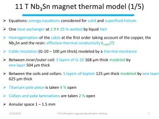
Motivation • Within the framework of the European project EuCARD, a Nb3Sn high field accelerator magnet is under design to serve as a test bed for future high field magnets and to upgrade the vertical CERN cable test facility, Fresca 2. • Calculation of the maximum temperature rise in the magnet during AC losses. • Calculation of magnet thermal – flow behavior during the quench detection event. • Implementation of superfluid helium in comercial software - ANSYS CFX software.
Outline • Motivation • Two – fluid model • Simplified model of He II • Validation of simplified model Steady state modeling • Modeling of thermal – flow process during AC losses in Nb3Sn magnet – steady state • Description of Fresca II magnet; • 3D computational region, assumption and boundary conditions; • Mesh; • Numerical results. Unsteady state modeling • Modeling of thermal process during quench heating – unsteady state model • Geometry and mesh; • Numericalresults. • Conclusions
Two – fluid model • Density of superfluid helium (1) • Density flux (2) • Continuity equation (3) • Momentum equations for the total fluid (4) • Momentum equations for the superfluid component (5) • Entropy equation (6)
Outline • Motivation • Two – fluid model • Simplified model of He II • Validation of simplified model Steady state modeling • Modeling of thermal – flow process during AC losses in Nb3Sn magnet – steady state • Description of Fresca II magnet; • 3D computational region, assumption and boundary conditions; • Mesh; • Numerical results. Unsteady state modeling • Modeling of thermal process during quench heating – unsteady state model • Geometry and mesh; • Numericalresults. • Conclusions
Simplified model of He II (Kitamura et al.) • The momentum equations for the superfluid component is simplified to the form (the thermomechanical effect term and the Gorter-Mellink mutual friction term are larger than the other) Superfluid component: Normal component: Momentum equation
The system of equation for He II simplified model • Continuity equation (1) • Momentum equation: (2) where: -the convectional acceleration; - the viscous effect. • Energy equation: (3)
Outline • Motivation • Two – fluid model • Simplified model of He II • Validation of simplified model Steady state modeling • Modeling of thermal – flow process during AC losses in Nb3Sn magnet – steady state • Description of Fresca II magnet; • 3D computational region, assumption and boundary conditions; • Mesh; • Numerical results. Unsteady state modeling • Modeling of thermal process during quench heating – unsteady state model • Geometry and mesh; • Numericalresults. • Conclusions
Validation of the simplified model 1. For He II (fluiddomain) 2. Insulation (solid domain) 3. Kapitza resistance Rk as a function of temperature Boundary conditions on left and right – adiabatic condition on the top – constant temperature Tb=1.95 K on the bottom – constant heat flux q=const on all walls and
Validation of the simplified model q = 0.70 W/cm2 q = 1.39 W/cm2 q = 2.09 W/cm2 (near CHF) Solid domain Solid domain Solid domain Temperature distribution in He II and solid (partially) domains for the temperature of 1.95 K and 0.70, 1.39 and 2.09 W/cm2 of heat fluxes at steady state condition
Validation of the simplified model Superfluid component Normal component Total velocity Top Bottom The velocity distribution and the streamlines of total velocity, superfluid and normal components in the region near the bottom and the top of He II domain for the highest heat flux of 2.09 W/cm2
Validation of the simplified model The comparison between analytical and numerical maximum temperature for applied heat flux at the bottom of solid domain One dimensional turbulent heat transport equation analitycal solution The comparison between applied and calculated (from difference between normal and superfluid components) heat fluxes at the bottom and top of He II domain
Outline • Motivation • Two – fluid model • Simplified model of He II • Validation of simplified model Steady state modeling • Modeling of thermal – flow process during AC losses in Nb3Sn magnet – steady state • Description of Fresca II magnet; • 3D computational region, assumption and boundary conditions; • Mesh; • Numerical results. Unsteady state modeling • Modeling of thermal process during quench heating – unsteady state model • Geometry and mesh; • Numericalresults. • Conclusions
Description of Fresca II magnet • MAGNET SPECIFICATION • type: block coil, 156 conductors in one pole; • free aperture: 100 mm; • total length: 1600 mm; • outside diameter: 1030 mm; • magnetic field: 13 T; • OPERATING PARAMETERS • coolant: superfluid and/or saturated helium; • temperature: 1.9 K and/or 4.2 K; • temperature operating margin: 5.84 at 1.9 K and 3.54 K at 4.2 K
3D computational region, assumption and boundary conditions • Assumptions • Two types of boundary conditions: • Constant bath temperature of 1.9 K on walls (red lines); • Symmetry (yellow lines); • Thermal conductivity as function of temperature; • Perfect contact between solid elements; • Calculations are carried out for CUDI model (AC loss due to ISCC losses, non-homogenous spreads) • He II between yoke and pad laminations (200 mm) Geometry and boundary conditions applied during simulations Cross –section of the numerical domains He II region
Mesh About 2 mln of structural elements 2.5 mln of nodes
Thermal conductivity of materials Source: Cryocomp Software v 3.06 Metalpak Software v 1.00
Numerical results Details of the temperature map in the conductors Details of the temperature map in the conductor for solid model (S. Pietrowicz, B. Baudouy, Thermal design of an Nb3Sn high fieldacceleratormagnet, CEC Conference, 2011, Spokane, USA) The distribution map of temperature in the magnet (the plane is located on symmetry of helium side)
Numerical results Total velocity Superfluid component Normal component
Outline • Motivation • Two – fluid model • Simplified model of He II • Validation of simplified model Steady state modeling • Modeling of thermal – flow process during AC losses in Nb3Sn magnet – steady state • Description of Fresca II magnet; • 3D computational region, assumption and boundary conditions; • Mesh; • Numerical results. Unsteady state modeling • Modeling of thermal process during quench heating – unsteady state model • Geometry and mesh; • Numericalresults. • Conclusions
Modeling of thermal process duringquench heating – unsteady state model • Assumptions • Two types of boundary conditions: • Constant temperature of the bath and Kapitza resistance on walls (red lines); • Symmetry (yellow lines); • Thermal conductivity and capacity as a function of temperature; • Perfect contact between solid elements; • Bath temperature1.9 K • Heating power of quench heaters 50 W/cm2(the magnetisheated 25 ms afterquenchdetection) Heaters Localization of the heaters Details of the mesh Dimensions of the heater and base of heater
Modeling of thermal process duringquench heating – unsteady state model Heating Heating
Modeling of thermal process duringquench heating – unsteady state model 4 – 5 ms Temperature evolution at selected points Has to be validated
Outline • Motivation • Two – fluid model • Simplified model of He II • Validation of simplified model Steady state modeling • Modeling of thermal – flow process during AC losses in Nb3Sn magnet – steady state • Description of Fresca II magnet; • 3D computational region, assumption and boundary conditions; • Mesh; • Numerical results. Unsteady state modeling • Modeling of thermal process during quench heating – unsteady state model • Geometry and mesh; • Numericalresults. • Conclusions
Conclusions • The simplified model for calculations of the thermal – flow phenomena was developed and applied in ANSYS CFX Software which is based on FVM (Finite Volume Method) • The model has been validated on the simple geometry and compared with the analytical solution. The maximum error is varied between 0.6 and 1.7 %. • The calculation at steady state conditions for the CUDI model of AC losses of Nb3Sn magnet – Fresca II has been carried out. In comparison to (with) the solid model (without helium), adding He II to the structure decreased maximum temperature rise. • The simulation of transient process in He II during the quench heating has been performed.