Download
1 / 21
220 likes | 388 Views
TEM Prep using FIB and Kleindiek Micro-Manipulator. General Reminders, Tips and Tricks. When in FIB view, work quickly to do what is needed and then freeze the image to avoid damage from scanning Always protect surface with Pt or W when using the FIB to ensure much smoother cuts

E N D
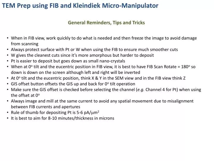
TEM Prep using FIB and Kleindiek Micro-Manipulator General Reminders, Tips and Tricks • When in FIB view, work quickly to do what is needed and then freeze the image to avoid damage from scanning • Always protect surface with Pt or W when using the FIB to ensure much smoother cuts • W gives the cleanest cuts since it’s more amorphous but harder to deposit • Pt is easier to deposit but goes down as small nano-crystals • When at 0o tilt and the eucentric position in FIB view, it is best to have FIB Scan Rotate = 180o so down is down on the screen although left and right will be inverted • At 0o tilt and the eucentric position, think X & Y in the SEM view and in the FIB view think Z • GIS offset button offsets the GIS up and back for 0o tilt operation • Make sure the GIS offset is checked before selecting the channel (e.g.Channel 4 for Pt) when using the offset at 0o • Always image and mill at the same current to avoid any spatial movement due to misalignment between FIB currents and apertures • Rule of thumb for depositing Pt is 5-6 pA/mm2 • It is best to aim for 8-10 minutes/thickness in microns
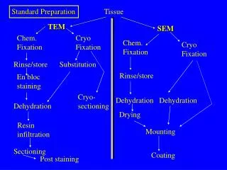
TEM Prep using FIB and Kleindiek Micro-Manipulator Overview e-beam deposition of Pt FIB deposition of Pt FIB milling of trapeziums FIB “U-Cut” to create free-standing structure (except for remaining tab) Pt welding to micro-manipulator FIB milling to etch remaining tab Attaching section to TEM Grid FIB milling to thin section to TEM thickness Final low kV FIB milling to reduce milling damage to section
e-Beam Deposition of Pt Start at 1 kV, 120 mm aperture, and high current mode Find area of interest and set up eucentric and coincidence conditions Make sure that SCM is off so that the touch alarm activates At 0o tilt, make sure the GIS offset is checked and insert Pt Use the reduced area function and open the Pt valve to deposit a Pt strip over the feature of interest for a few minutes
FIB Deposition of Pt • Remove the GIS and tilt to 54o • Insert the GIS (offset unchecked) • Select 100 pA as the imaging current (Too high of current will cause milling rather than deposition) • In FIB view, find the area of interest and freeze the image • Deposit Pt strip using conditions shown below • Rule of thumb is to deposit Pt around 5-6pA/mm2 (size dependent; e.g. larger area may be half this value) and aim for 8-10 minutes/thickness in mm
FIB Milling of Trapeziums • Mill trapeziums on each side of the Pt strip at 54o using the conditions shown below • Use of XeF2 flashing for improved etching is optional (insert XeF2 channel and manually flash) • Conditions below are for InAs • Harder materials (e.g. Si) may need higher milling currents (~5-10 nA) • The trapezoid should extend past the Pt strip by at least 2-3 mm At least 2-3 mm overhang past Pt strip
FIB Milling of Trapeziums InAsRedeposition Artifact • For the training session, we used InAs which is hard to mill properly • Lower FIB currents and XeF2 flashing were used to help with better milling • Below shows an example of redeposition after our first attempt
FIB Milling of Trapeziums Fine Polishing Clean up the face of the trapezoid by etching a fine rectangle at 54.5o using the conditions shown below
FIB Milling of Trapeziums Fine Polishing Clean up the other face of the trapezoid by etching a fine rectangle at 53.5o using the conditions shown below
FIB Milling of the U-Cut First Cut Go to 7o tilt and scan rotate the FIB image 180o Important to use deposition mode (even though we are etching) so we can watch the structure break free in SEM image while the FIB milling is occuring Set time for 4 minutes but stop when it etches through
FIB Milling of the U-Cut Second Cut Remain at 7o tilt and scan rotate the FIB image 180o Important to use deposition mode (even though we are etching) so we can watch the structure break free in SEM image while the FIB milling is occuring Set time for 4 minutes but stop when it etches through
FIB Milling of the U-Cut Final Cut • Remain at 7o tilt and scan rotate the FIB image 180o • Important to use deposition mode (even though we are etching) so we can watch the structure break free in SEM image while the FIB milling is occuring • Set time for 4 minutes but stop when it etches through • Free standing structure remains except for small tab attached to the bulk of the sample
Pt Welding to the Micro-Manipulator • Tilt to 0o • Using the camera view, bring in the Kleindiek probe into the vicinity of the sample stage making sure it will clear the sample height • Continue to move the probe so that it is visible in the low magnification SEM view • Make sure that the GIS offset is checked and bring in the GIS Pt source • Turn on the SCM so the touch alarm does not go off when bringing in the micro-manipulator probe • Lower the micro-manipulator probe such that it is about 1 mm above the sample • Move the probe to the region behind the behind the slice and centered in the trench • Continue to move down until the probe is about 500 mm above the slice, keeping it centered • Open the Pt valve • Opening the valve causes the probe to vibrate so this must be down before the probe contacts the sample
Pt Welding to the Micro-Manipulator • Switch to the FIB view using 20 pA to image (lower is better, but the contrast is low) • Move the sample down until it is visible in the FIB view • Align in the SEM view over the corner • Move down into contact using the FIB view (Z) and SEM (X & Y) view • Switch the FIB imaging current to 10 pA and freeze the image • Deposit Pt on the section and probe using the conditions shown below • Note this image has the support bar on the opposite side of where it normally is with respect to the probe • Pt deposition should be done at 10 pA current for 6-8 minute • Checking for attachment can be done by touching the SEM table and looking at the vibration coupling in the image
FIB Milling to Etch Remaining Tab • Use 100-200 pA FIB view imaging and a reduced area FIB image to etch away the remaining tab to the substrate to etch the section free • It will be apparent when the section has been etched free (not shown) • Move M ↑ (stage goes down, M goes to higher values) to release the section now attached to the micro-manipulator probe
Attaching Section to TEM Grid Remove the GIS Go to Using camera view, remove the micro-manipulator and section to a safe location outside of the SEM stage Move the stage to the TEM grid position and re-establish the eucentric and coincidence positions At 0o tilt, turn SCM off and bring in the GIS Pt Open the Ptvavle and turn the SCM on so the stage alarm won’t go off while attaching the section to the TEM grid Using the micromanipulator controls and the camera, SEM and FIB views, move the section into position above the TEM grid
Attaching Section to TEM Grid First Pt Weld • Deposit Pt onto the grid and section and shown below • Although the recipe below is four 4 minutes, we did two steps of 6 minute depositions using 10 pA 1st Pt weld
Attaching Section to TEM Grid Second Pt Weld • Deposit Pt onto the grid and section and shown below • Although the recipe below is four 4 minutes, we did two steps of 6 minute depositions using 10 pA 2nd Pt weld
Attaching Section to TEM Grid Removing/Etching Away Micro-Manipulator Recipe not copied but etch using Deposition Mode, 30 kV:100 pA, No Gas ID, Frequency X 20000, Frequency Y 1 Etch 6 minutes but stop when done Remove micro-manipulator to safe or parked location away from stage using camera, SEM, and FIB views Etching Away Micro-Manipulator
FIB Milling to Thin Section to TEM Thickness First Side • With the section now attached to the TEM grid, go to 54.5o stage tilt and use the FIB to thin the section using the conditions shown below • When thinning, you want to see some curtain at the bottom of the slice. This adds some additional support (This is controlled by the milling depth) • Near end of thinning SEM beam reduced to 1 kV because sample becomes transparent at 5 kV. • The final window should be about 5 to 8 microns – sample width about 15 to 20 microns • XeF2 flashed just prior to final thinning on both sides of sample to clean up the In balls • Sample needs to be thin, but greater than 120 nm as the thickness of the XeF2 reaction is about 60 nm thick (from previous measurements)
FIB Milling to Thin Section to TEM Thickness Second Side • Tilt to 0o, perform a 180ocompucentric rotation and then tilt back up to 54.5o and FIB the other side using the conditions shown below • When thinning, you want to see some curtain at the bottom of the slice as this adds some additional support (This is controlled by the milling depth) • Near end of thinning SEM beam reduced to 1 kV because sample becomes transparent at 5 kV. • The final window should be about 5 to 8 microns – sample width about 15 to 20 microns • Look for the Pt receding to the top of the sample in SEM view while milling as this is the indicator to stop (final endpoint) • Watch for uneven recession – our sample bowed and the two ends receded before the middle
Final Low kV FIB Milling to Reduce Milling Damage to Section • Tilt sample to 45o and use low kV (5 kV: 100 pA) final polishing in deposition mode for 10-60 seconds on each side • Time needed is sample dependent (TEM imaging is ultimate test) • Final polishing is being done on the opposite side from the SEM view so cannot monitor progress but can see punch through