Download

1 / 15
180 likes | 490 Views
IR OBSTACLE DETECTION TO ACTUATE LOAD. Introduction. This system is used to turn on a load whenever the IR ray is blocked by an object, person. A 38 KHz signal is generated by 555 timer which is feed to the IR diode

E N D
IR OBSTACLE DETECTION TO ACTUATE LOAD
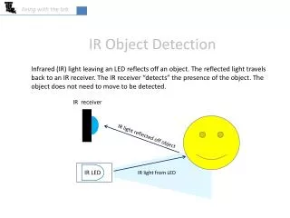
Introduction This system is used to turn on a load whenever the IR ray is blocked by an object, person. A 38 KHz signal is generated by 555 timer which is feed to the IR diode which in turn produces an IR ray of 38Khz.This ray is received by tuned IR receiver continuously. Whenever there is an obstacle to the IR ray the receiver sends a signal to the microcontroller which actuates a load, from its output.
EMBEDDED SYSTEMS Definition for :- EMBEDDED SYSTEMS • A combination of hardware and software which together form a component of a larger machine. • An example of an embedded system is a microprocessor that controls an automobile engine. • An embedded system is designed to run on its own without human intervention, and may be required to respond to events in real time.
MICRO CONTROLLER AT89S52 • Compatible with MCS®-51 Products • 8K Bytes of In-System Programmable (ISP) Flash Memory • 4.0V to 5.5V Operating Range • Crystal Frequency 11.0592MHZ • Three-level Program Memory Lock • 256 x 8-bit Internal RAM • 32 Programmable I/O Lines • Three 16-bit Timer/Counters • Eight Interrupt Sources • Full Duplex UART Serial Channel • Watchdog Timer
BC547 • The BC547 transistor is an NPN Epitaxial Silicon Transistor. • The BC547 transistor is a general-purpose transistor in small plastic packages. • It is used in general-purpose switching and amplification BC847/BC547 series 45 V, 100 mA NPN general-purpose transistors. • Whenever base is high, then current starts flowing through base and emitter and after that only current will pass from collector to emitter
RELAY • IT IS A ELECTRO MAGNETIC SWITCH • USED TO CONTROL THE ELECTRICAL DEVICES • COPPER CORE MAGNETIC FLUX PLAYS MAIN ROLE HERE
555 TIMER • The 555 Timer IC is an integrated circuit (chip) implementing a variety of timer and multivibrator applications. • The original name was the SE555 (metal can)/NE555 (plastic DIP) and the part was described as "The IC Time Machine". • Depending on the manufacturer, the standard 555 package includes over 20 transistors, 2 diodes and 15 resistorson a silicon chip installed in an 8-pin mini dual-in-line package (DIP-8)
PIN DIAGRAM OF 555 • The 555 timer IC is a simple 8 pin DIL package IC. • It can: • be used as a monostable • be used as an astable • source or sink 100mA • use supply voltages of 5v to 15v • disrupt the power supply - use a decoupling • capacitor!
IR LED An IR LED, also known as IR transmitter, is a special purpose LED that transmits infrared rays in the range of 760 nm wavelength. Such LEDs are usually made of gallium arsenide or aluminum gallium arsenide. They, along with IR receivers, are commonly used as sensors. The appearance is same as a common LED. Since the human eye cannot see the infrared radiations, it is not possible for a person to identify whether the IR LED is working or not, unlike a common LED. To overcome this problem, the camera on a cell phone can be used. The camera can show us the IR rays being emanated from the IR LED in a circuit.
TSOP 1738 RECEIVER PIN DIAGRAM • It’s a standard IR remote control • receiver • supporting all major transmission codes • Pin1 – Connected to Ground • Pin2 – Connected to Vcc • Pin3 – Output Pin • In Between 1st Pin and 2nd Pin we have • to connect one Capacitor • TSOP 1738 Receives 14—bit of data
TSOP 1738 FEATURES • Photo detector and preamplifier in one package • Internal filter for PCM frequency • TTL and CMOS compatibility • Output active low • Low power consumption • High immunity against ambient light • Continuous data transmission possible (up to 2400 bps) • Suitable burst length .10 cycles/burst
SOFTWARE REQUIREMENTS PROGRAMMING LANGUAGES Embedded C , ALP (Assembly Language) COMPILERS: Keil 2.0/3.0uv DUMPING SOFT WARE: Using Micro controller flash Software we are dumping our HEX Code into Micro Controller