Download

1 / 34
1.2k likes | 4.18k Views
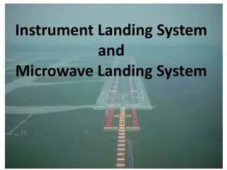
Instrument Landing System ILS. GP Freq. = 3 x LLZ Freq. ILS System. ILS Ref. Point. UHF 328.6 - 335.4 MHz. 50ft. Threshold. VHF 108.1 - 111.95 MHz. A typical ILS installation. Radio Navigation – Chapter 6. ILS Localiser Antenna. 35°. 1 50Hz. 90Hz. Correct signals. 150Hz sector.

E N D
GP Freq. = 3 x LLZ Freq. ILS System ILS Ref. Point UHF 328.6 - 335.4 MHz 50ft Threshold VHF 108.1 - 111.95 MHz
A typical ILS installation. Radio Navigation – Chapter 6
35° 150Hz 90Hz Correct signals 150Hz sector Equisignal 90Hz sector 20% overlap(DDM) 35° False signals Modulation pattern - localiser
The required localizer horizontal coverage. (10NM) (18NM) Steep angle of approach GP (> 4°) Radio Navigation – Chapter 6
P = 600m above THR, or 300m above terrain, whichever is highest The required vertical coverage of the localizer. Radio Navigation – Chapter 6
Glide Path location 27 150m 300m
GP Coverage Upper limit = ° x 1.75 Lower limit = ° x 0.45 e.g. 3° x 1.75 = 5.25° 3° x 0.45 = 1.35° Steep angle of approach = 8 NM
Critical & Sensitive Areas • The ILS critical area is an area of defined dimensions about the localizer and glide path antennae, where vehicles, including aircraft, are excluded during all ILS operations. The area is protected to prevent aircraft or vehicles causing unacceptable disturbances to the signal-in-space.
Critical & Sensitive Areas • The ILS sensitive area extends beyond the critical area, where movement or parking of aircraft and vehicles is controlled to prevent interference to the ILS signal.
CDI – Course Deviation Indicator Max. safe GP deviation NAV warning flag Glideslope FSD = 0.7° Localiser FSD = 2.5° GS warning flag
HSI – Horizontal Situation Indicator • The course setting is independent from the heading. • An error on the heading does not affect ILS indications Radio Navigation – Chapter 6
“Bending” is a single angular displacement from the approach path • With “scalloping”, the guidance beam direction varies from side to side of the intended approach path. Radio Navigation – Chapter 6
Simplified diagram of glide path radiation pattern. Radio Navigation – Chapter 6
Detailed GP pattern = 4 x (12) = 3 x (9) = 2 x
Some localizers also transmit in the opposite direction of the ILS in bound course and the signal can be received when flying behind the aerial. • This signal is called the back beam and should not normally be used, unless there is a published back course procedure. Radio Navigation – Chapter 6
ILS – Design Categories • Category I – to a height of 60 metres (200 ft) above the horizontal plane containing the threshold • Category II – to a height of 30 metres (100 ft) above the horizontal plane containing the threshold • Category III – with the aid of ancillary equipment when necessary, down to and along the runway.
ILS Protection • Channel spacing designed to prevent interference • Mandatory FM immunity filters fitted to ILS receivers
ILS Monitoring & Shutdown • Cat I – 6 seconds • Cat II/III – 2 seconds
ILS Identification • RWY 24 – ‘INN’ • RWY 06 – ‘IMM’
Jeppesen Approach Plate – Madrid, Barajas Flying the ILS approach
Flying the glide path Rule of thumb (3° GP) • Height on approach (feet) = Distance from THR(NM) x 300 + 50 ft • Rate of descent (fpm) = Ground speed (kt) x 5
Marker Beacons • Operate on 75 MHz • Usually fan-shape • Often co-located with NDB, e.g. ‘LOM’, ‘LMM’ • Can be ‘Z’ markers (‘dog-bone’ shape)
The marker receiver control unit consists of three coloured lamps and a sensitivity switch. AIRWAY Radio Navigation – Chapter 7
Questions • What is the frequency range of ILS? • 108 - 112 MHz (odd decimals) • What are the localizer modulation frequencies? • 90Hz (left), 150Hz (right) • How can you work out the approximate GP frequency? • LLZ freq x 3 • How do you tune into the GP frequency? • By selecting a paired LLZ VHF frequency • Where is the GP located? • 300m from the THR & 150m from the runway
Questions • What is the difference in depth of modulation (DDM) on the centreline of the runway? • 20% • Where is the ILS reference point? • 50ft above the threshold • What is the rule of thumb formula for calculating height on approach (3° GP) • Distance from touchdown (nm) x 300 + 50ft • What is the rule of thumb formula for calculating rate of descent? • = 5 X G/S(kt) fpm
Questions • At what angle does the first false GP appear? • 2 x GP angle • A Cat 1 ILS will guide an aircraft down to what height? • 200ft • What is the coverage of the LLZ at 25NM range? • 10° • If there is deviation on the heading indication of a HSI, how will it affect the ILS indications? • No effect
Questions • When can a back course procedure be used? • When there is an authorised published procedure • What is missing from a back course approach? • Glide path • What frequency do marker beacons operate on? • 75MHz
Questions • What are the characteristics of an OM? • Blue light, 2 dashes/sec, 400 Hz tone • When must an aircraft not taxi into the sensitive area, unless cleared? • When Cat II/III operations are in progress • What is the sequence of marker colours when flying an ILS approach? • Blue, amber, white