Download
1 / 15
150 likes | 342 Views
NSLS-II Beam Containment System. R. Casey Accelerator Systems Advisory Committee October 22, 2009. Beam Containment System. Beam containment system (BCS) is the term used to describe the various active and passive devices designed to:

E N D
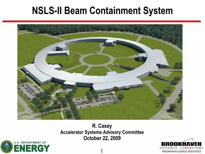
NSLS-II Beam Containment System R. Casey Accelerator Systems Advisory Committee October 22, 2009
Beam Containment System • Beam containment system (BCS) is the term used to describe the various active and passive devices designed to: • Localize electron beam losses to selected (well shielded) areas in the accelerator enclosures • Detect excessive beam loss outside of well shielded areas • Provide linkage to other systems to mitigate excessive losses when detected • Area radiation monitoring systems complement BCS function by providing direct measurement of radiation levels in occupied areas.
Beam Containment System (cont.) • Objective - alert operators to excessive beam losses that create potential for increased radiation levels in occupied areas and provide mitigation as required. • Mitigation measures include: • operator warnings and alarms • direct curtailment of injection
Beam Loss Assumptions in Shielding Design Injection region shielded for 3 GeV at 1 Hz injection rate Extraction region shielded for 3 GeV at 1 Hz extraction rate Injection region shielded for 200 MeV and I Hz injection rate
Implications of Shielding Design • Abnormal operating conditions need to be evaluated. • Additional engineering or administrative controls will be specified based on severity of radiation levels under fault conditions. • An area radiation monitoring system is needed to detect excessive radiation in occupied areas and will serve as the primary safety system to protect against radiation producing faults. • BCS is provided to detect abnormal conditions or abnormal beam losses and provide warning to machine operators. System will also inhibit injection systems on alarm.
Actions Taken to Define BCS Systems • The radiological consequences of abnormal operating conditions have been described and analyzed as part of on-going safety assessments • BCS task force appointed and work is underway to finalize design • BCS functional requirements based on radiological analyses have been presented • BCS components identified
BCS Task Force Setup to Define and Document BCS • Task Force Members: S. Kramer, Y. Li, I. Pinayev, P.K. Job, D. Hseuh • Other stake-holders: R. Casey, O. Singh, P. Cameron, B. Delasio • Working Group has been meeting regularly since Spring, 2009
Examples of Abnormal Events and Consequences • Full beam loss in Linac at design beam current (15 nA) • Max. dose rate – 8 mRem/h • Full beam loss in Booster injection region at 200 MeV • Max. dose rate – 1 mRem/h with 1 Hz injection • Full beam loss in Booster extraction region at 3 GeV • Max. dose rate – 2.5 mRem/h with 1 Hz injection
Abnormal Events and Consequences (cont.) • Full beam loss in remainder of booster at 3 GeV • Max. dose rate – 1500 mRem/h above berm, 375 mRem/h in injection building with 1 Hz injection • Full injected beam loss in Storage Ring (SR) injection region • Max. dose rate – 2.5 mRem/h with 1 Hz injection • Full injected beam loss at one point in SR non-injection region • Max. dose rate – 400 mRem/h with 1 Hz injection
Current Definition of BCS Components • Scrapers in SR injection region (4) • R& D at NSLS for thin scraper design planned for FY 10 • Current Transformers (5) • Linac (ICT) • Linac to Booster transfer line (ICT) • Booster (DCCT) • Booster to SR transfer line (ICT) • SR (DCCT) • Beam loss monitors (Type and # TBD) • SR at potential high loss points (steering and energy dispersive maxima) • R & D at NSLS for Cerenkov BLM planned for FY 10
Area Radiation Monitors • 2 - linac klystron gallery • 6 - injection building • 30 - Storage ring wall (1 per cell) • 6 - FOE wall Budgeted for 60 monitors
BCS Functions • Monitor and limit beam current in injection system and SR • Detect high beam losses in injection or extraction processes in booster by comparison of current transformers (CTs) in transport line and booster • Detect high beam losses in injection to SR by comparison of CTs in transport line and SR • Provide scrapers and monitors in SR injection region to localize and confirm losses in that region (need for additional monitors in non-injection areas being evaluated) • Alert machine operators to abnormal conditions and inhibit continued injection as warranted
Interface between Systems for BCS • Insure signals are available at rate needed, insure integrity of communication link • Define the responsibility for calibration of these signals and their maintenance • Issue Warnings if beam loss limit is being approached, suggest operator action needed • Limit exceeded at present injection rate, issue Alarm that action is required within prescribed time. • If exceeded for significant time interval, remove injection permit through BCS control network Warnings & Alarms to systems and operator Linac & transport CT signals BCS Micro Booster injection OK Storage ring injection OK Beam loss location OK Permit Injection On/Off Booster and transport CT signals SR CT signals Beam loss location monitors BCS Controlled Device Interface Box Injection On/Off
BCS Summary & Look Ahead • BCS task force is appointed and work is underway. BCS function specified. • Specification of BCS components is almost complete, more work required to specify location and type of beam loss monitors and ddesign of scrapers. • Warning and alarm set points for BCS will be established through fault testing and radiation measurements during commissioning. • BCS components will be subject to configuration control during installation, testing, operation, maintenance, and modification. • BCS interlocking functions are intended for routine operation. During commissioning and other times of machine studies, BCS interlocking may be temporarily removed. Protective function will be provided through work controls approved for the time period of the study.