Download
1 / 36
380 likes | 578 Views
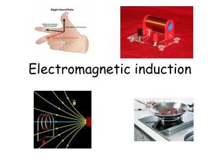
Lectures 13 and 14 Electromagnetic induction. Introduction

E N D
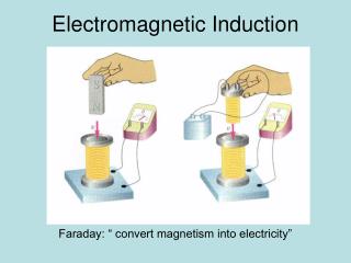
Introduction In the previous lectures we saw that when a current passes through a wire then a magnetic field is produced. It is reasonable to guess that there might be the reverse effect: if a wire is passed through a magnetic field then a current is produced. This effect, known as electromagnetic induction, was discovered in 1831-1832 during a series of experiments by Michael Faraday.
Faraday’s Experiments Mutual inductance: two coils A and B are arranged such that when a current flows in A some of the magnetic flux produced links (i.e. crosses) B. If the current through A changes then a current is induced in B.
Relative motion: a coil is placed such that the magnetic flux from a source M (this may be a magnet or a current) links it. If relative motion occurs between the coil and the source such that the flux linking the coil changes then a current is induced in the coil.
Cutting of flux by a conductor: when part of a circuit moves and, in doing so, cuts magnetic flux then a current is induced in the circuit.
Electromotance (voltage) or current?: the induced current is proportional to the conductance of the circuit. Hence a given change produces a definite electromotance (or electromotive force e.m.f – the ability to drive current around a circuit – related to voltage) rather than a definite current. • Self induction: an electromotance is induced in a circuit due to changes in its own current. • The magnitude of the induced electromotance is proportional to the rate of change.
The results of Faraday’s experiments are described by his laws of electromagnetic induction, summarised as follows • An electromotance is induced when • A rigid stationary circuit is placed in a time varying magnetic field • A rigid circuit moves in a steady B-field such that the magnetic flux through the circuit changes • Part of a circuit moves and in doing so cuts magnetic flux • Effect 1 is sometimes known as transformer electromotance and effects 2 and 3 as motional electromotance.
Lenz’s Law Faraday’s laws do not give the direction or sense of the induced electromotance or current. This is given by Lenz’s law which states ‘whenever a change produces an induced current the direction of flow of this current is such as to oppose the change causing it’.
Definition 1 Magnetic flux: This is defined in the same way as electric flux. If a magnetic field B passes through a surface A (described by a vector A) then the flux through A is =BA (i.e. it is the component of B normal to the surface multiplied by the area of the surface).
Definition 2 Electromotance (or electromotive force e.m.f) The electromotance is defined as the energy or work done per unit charge (Qt) when it is moved around a closed path L. (the final term results because F/Qt=E) The units of electromotance are the Volt (V). Because for electrostatics , static charges are unable to produce an electromotance.
Motional electromotance Consider the conductor in the figure which is moving with respect to the magnetic field B. Charges within the conductor experience a magnetic force given by F=QvB and hence an effective electric field E=vB.
If the conductor is part of a complete circuit then this E-field will cause a current to flow around the circuit. Because this E-field results from the effect of a magnetic field and not static charges (and as we will see is capable of producing an electromotance) we denote it as EM to distinguish it from electrostatic fields which we denote as ES. If the E-field EM exists along an element dl of the moving conductor then an electromotance d =EMdl= (vB)dl results.
Because of the form of this result it is only the components of v and dl which are perpendicular to the B-field (v┴ and dl┴ respectively) which are important. Hence the electromotance can be written in the non-vector form d =v┴Bdl┴ For a complete circuit the total electromotance is given by the line integral
Motional electromotance in terms of flux cutting The above result can also be expressed in terms of the rate of change of flux cutting. In time dt the element dl┴ moves a distance v┴dt and hence sweeps out an area v┴dtdl┴. The flux cut is hence this area multiplied by the field d= v┴dtdl┴B. Hence
but this last result is identical to the result for the motional electromotance derived previously so we have (where is the flux cut) This result can be shown to be a general one which applies to all types of electromagnetic induction (not just motional). A negative sign is inserted in the equation to account for Lenz’s law ( is the flux linking the circuit) This equation fully summarises Faraday’s law of electromagnetic induction.
Worked example A coil has an area A and contains N turns. If the coil is rotated with an angular velocity in a uniform magnetic field B, find the induced electromotance. What is the maximum electromotance if B=0.1T, A=5x5cm2, N=5000 and the coil is rotated by 100 turns/second?
Worked example A metal disc of radius a is rotated with angular velocity . If there is a uniform magnetic field B normal to the surface of the disc what electromotance is generated between the centre and rim of the disc? V a B
Worked example In the previous example of the spinning disc in which direction would the induced current flow?
Induced currents and charges If the flux through a circuit changes then an electromotance is produced and, from Ohm’s law, a current I=/R, where R is the resistance of the circuit, will flow. If the flux through the circuit varies from an initial value i at time tito a final value f at time tf (i-f=) then the total charge which flows in the circuit is
The differential form of Faraday’s law Faraday’s law tells us that a new type of electric field (EM) is produced in situations where the flux through a circuit changes. Although so far we have considered the effects of EM on conductors, EM will be present even in the absence of these conductors (in a similar way to the existence of electrostatic fields (ES) independent of the presence or not of any charges).
Hence the electromotance can be calculated around any arbitrary closed path L in free space but the flux can be written as where S is any surface enclosed by the path L. Hence
The order of integration and differentiation on the right hand side of this equation can be reversed and the left hand side can be transformed into a surface integral by applying Stoke’s theorem Because the second and third terms contain an integral over the same surface S the arguments of the two integrals must be equal at any given point. Hence
At any point in space the total E-field E is the sum of ES and EM E=ES+EM Because ES=0 and E=ES+EM we can write finally This is the fourth Maxwell equation.
Worked example Show that the equation is dimensionally correct
It can also be shown that the divergence of EM is always zero. EM=0 Hence E=/0as for purely electrostatic fields.
Self-inductance For any circuit the magnetic field at any point is proportional to the current Iflowing in the circuit. Hence the magnetic flux which links the circuit is also proportional to I. The constant of proportionality (which is a function of the shape and size of the circuit) is known as the self-inductance L. =LI
The unit of self-inductance is the Henry (H). A device designed to exhibit a specific value of self-inductance is known as an inductor. When the current through a circuit changes an electromotance or voltage is produced, given by the negative sign indicates that the induced voltage has a direction which opposes the change in I.
Calculation of self-inductance A solenoid: It can be shown that for a helically wound solenoid with a length much greater than its diameter that the field within the solenoid is approximately constant and had a value 0nI where n is the number of turns per unit length. The flux across each turn of area A is hence A0nI
and if the solenoid has a length l and hence nlturns, the total flux is A0n2Il Using the definition of L: L=/I L= A0n2l
Worked example A system consists of two coaxial hollow cylinders of radii a and b (b>a) and of infinite length. One cylinder carries a current I, the other a current –I What is the magnetic field in the region between the cylinders? What is the self-inductance of the system?
Magnetic energy (a) In terms of self-inductance The electromotance or voltage across an inductor is V=LdI/dt. Hence the rate at which energy is stored is in the inductor (Power = voltage x current) =LIdI/dt
In time dt the energy stored by the inductor is LIdIso the total energy UM stored when the current increases from 0 to I is
(b) In terms of the magnetic field It was shown above that the self-inductance of a solenoid is L= A0n2land the field inside the solenoid is B=0nI. Hence substituting in for L and using the formula for B to eliminate I the magnetic energy stored by the solenoid is this result expresses the magnetic energy in terms of an energy density (1/2)B2/0 multiplied by the volume of the solenoid Al.
This can be shown to be a general result Magnetic energy density = This result can be compared with the similar result derived for the electrical energy density Electrical energy density =
Conclusions • Electromagnetic induction – experimental evidence • Laws of electromagnetic induction • Lenz’s law • Definition of magnetic flux • Definition of electromotance or electromotive force (e.m.f) • Motional electromotance • Motional electromotance in terms of flux cutting
Faraday’s law of electromagnetic induction • Induced currents and charges • The differential form of Faraday’s law • Self-inductance: definition and calculation • Magnetic energy in terms of self-inductance and magnetic fields