Download
1 / 26
270 likes | 473 Views
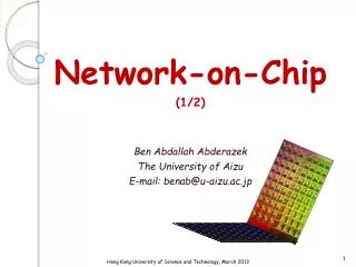
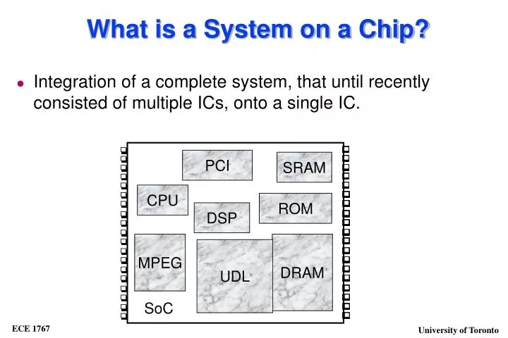
PCI. SRAM. CPU. ROM. DSP. MPEG. DRAM. UDL. SoC. What is a System on a Chip?. Integration of a complete system, that until recently consisted of multiple ICs, onto a single IC. Why? Complex applications Progress of technology allows it High performance Battery life

E N D
PCI SRAM CPU ROM DSP MPEG DRAM UDL SoC What is a System on a Chip? • Integration of a complete system, that until recently consisted of multiple ICs, onto a single IC.
Why? Complex applications Progress of technology allows it High performance Battery life Short market window Cost sensitivity Characteristics: Very large transistor counts on a single IC Mixed technology on the same chip (digital, memory, analog, FPGA) Multiple clock frequences Different testing strategies and test sets System Chips
SoC Target Applications • Telecommunications, networking: • ATM switches, Ethernet switches, bridges, routers • Portable consumer products: • Cellular phones, pagers, organizers • Multimedia: • Digital cameras, games, digital video • Embedded Control • Automotive, printers, smart cards, disk drives
What are embedded cores? • Core: Pre-designed, pre-verified complex functional blocks also termed IP, megacells, system-level macros, virtual components • Processor Cores: ARM, MIPS, IBM PowerPC, BIST logic • DSP Cores: TI, Pine, Oak • Peripherals: DMA Controller, MMU • Interface: PCI, USB • Multimedia: JPEG Compression, MPEG decoder • Networking: Ethernet Controller, ATM switches
Core Types . • Soft core • A synthesizable HDL description • Firm core • A gate-level netlist that meets timing assessment. • Hard core • Includes layout and technology-dependent timing information
Core Concerns • Cost-of-Test and Time-to-Market concerns have lead to a Core-Based Design approach. • Goal is to supply easy-to-integrate cores to the system-on-a-chip market. • Core design and core integration are major issues. • System-on-Board vs. System-on-Chip: • Analogy:Reuse of pre-designed components on a system • Difference: SoC components are only manufactured and tested in the final system
Core Test Challenges? • Distributed Design and Test Development • Test Access to Embedded Cores • SoC-Level Test Optimization • On top of: • Traditional Challenges:Trade-off test quality, test development time, IC cost, test application cost • New Deep-Submicron Design Challenges: by 2005 it is predicted 100nm technology, clock > 3.5 GHz, supply 0.9-1.2 V” • New Deep-Submicron Test Challenges: new defects such as noise, crosstalk, soft errors
Core Test Challenges? • Distributed development: test knowledge transfer includes test methods, protocols and pattern data, core-internal DFT. Core-based design and test is spread over company and time • Test Access to Embedded Cores: often # cores terminals > # IC pins. Need to test cores as stand-alone units: provide core access from IC pins and isolate cores when testing from other modules • SoC-Level Test Optimization: SoC consists of simple and complex cores, UDL, interconnect logic. SoC test should address all of this: • Test quality, cost, bandwidth and area • Trade-off between test vector count, application time, area and power
Core Test Challenges? • There is no direct access to the core cell ports from the primary inputs and primary outputs of the chip. • Creation of peripheral access often involves an additional DFT effort. • Core integration • Use of multiple cores within one design with different DFT strategies • Core Testing Strategy: • Decouple embedded core level test from system chip test • Identify adequate core test methodology • Create mechanism for core test access • Identify and implement system-chip level test methodology
Internal Core Test • The core integrator has little knowledge of the adopted core’s structural content. • Core builder won’t know which test method to adopt, the type of fault, or desired level of fault coverage. • Several versions of a core may be available, each using different parameters or a different DFT strategy. • The organization responsible for testing the overall chip should define the DFT and Test strategy. • If intellectual property (IP) is not an issue, a standard DFT approach can be used. • Nondisclosure agreements (NDA’s) may be adequate.
CUT CUT wrapper Generic Core Test Access Architecture sink source TAM TAM • Test Pattern Source and Sink: • Generates test stimuli and performs test analysis • Test Access Mechanism (TAM): • Transports test patterns to/from CUT • Core Test Wrapper: • Provides switching of core terminals to functional I/O or TAM
CUT CUT wrapper Generic SoC Test Access Architecture PCI SRAM CPU ROM source sink TAM TAM MPEG DRAM UDL SoC
Test Access Mechanism (TAM) • There are two parameters involved with a TAM: • TAM capacity (number of wires):needs to meet core’s data rate (minimum) and it cannot be more than bandwidth of source/sink (maximum). Trade-off between test quality, test time, area • TAM length (wire length): on/off chip source/sink. TAM length can be shortened if it is shared with other modules or is is shared with functional hardware • TAM Implementations:Multiplexed Access, Reused System Bus, Transparent, Boundary Scan
Test Access Mechanism (TAM) • Connect wire to all core • terminals and multiplex onto • existing IC pins • Test mode per core controls • multiplexer • Common for memories and • block based ASICs Core A Core A N Core A SoC
Test Access Mechanism (TAM) Benefits - Embedded core can be tested as stand alone device - Translation from core-level to system-level is easy - Simple silicon debug and diagnosis Drawbacks - Method is not scalable. If #core terminals > # IC pins => parallel to serial conversion => difficult at-speed testing - Area and control circuitry grows
Reused System Bus • Motivation: Many SoCs have an on-chip system bus that connects to most cores anyway. Reuse system bus as TAM is cheap w.r.t. siicon area Benefits - Low area Drawbacks - Fixed bus does not allow trade-offs (area, quality, test time) - Difficult to integrate scan design or BIST
Transparent TAM Transparent Path: path from source to sink with no information loss Examples of transparency: scan chains, arithmetic functions, embedded memories, blocks of basic gates AND, OR, INV, MUX PCI SRAM CPU source ROM CUT wrapper DRAM MPEG UDL sink SoC
Transparent TAM Benefits - Low area cost for TAM in case of reuse of existing hardware Drawbacks - Core test access depends on other modules - During core design, core environments are unknown. Core user has to add TAMs in the cores. - Translation from core-level to IC-level test might be complicated (e.g., latencies of cores)
Boundary Scan Methods • Isolation ring • Boundary scan chain • Internal (parallel) scan for sequential cores • Higher test application time. • Partial isolation ring • Place some core I/O’s in a boundary scan chain.
Boundary Scan: Isolation Ring • Boundary scan chain for accessing Core I/O’s • Internal scan chain. Chip UDL UDL Core
Boundary Scan: Partial Isolation Ring • Not all core I/O’s placed in boundary scan chain. • Need observability (for testing UDL 1) for core inputs omitted from boundary scan chain. • Need controllability (for testing UDL 2) for core outputs omitted from boundary scan chain. Chip UDL 1 UDL 2 Core
Core Test Wrapper • Wrapper’s Task: • Interface between core and rest of chip (TAM) • Switching ability between: • normal operation of core • core test mode • interconnect test mode (bypass mode) • Width adaptation: serial-to-parallel at core inputs, parallel-to-serial at core outputs
Core Test Wrapper wrapper wrapper wrapper bypass scan chain Core B Core B Core B scan chain scan chain scan chain scan chain scan chain scan chain test control block test control block test control block
Core Test Wrapper: Normal Mode wrapper wrapper wrapper scan chain Core B Core B Core B scan chain scan chain scan chain scan chain scan chain scan chain test control block test control block test control block
Core Test Wrapper: Test Mode wrapper wrapper wrapper scan chain Core B Core B Core B scan chain scan chain scan chain scan chain scan chain scan chain test control block test control block test control block
Core Test Wrapper: Bypass Mode wrapper wrapper wrapper CUT scan chain Core B Core B Core B scan chain scan chain scan chain scan chain scan chain scan chain test control block test control block test control block