Download
1 / 55
820 likes | 1.8k Views
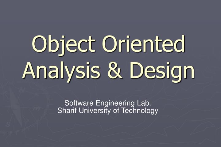
Object Oriented Analysis & Design. Software Engineering Lab. Sharif University of Technology. Agenda. Object-Oriented Concepts and Principles Object Oriented Analysis Object Oriented Design. Object-Oriented Concepts and Principles. Introduction. We live in a world of objects.

E N D
Object Oriented Analysis & Design Software Engineering Lab. Sharif University of Technology
Agenda • Object-Oriented Concepts and Principles • Object Oriented Analysis • Object Oriented Design
Introduction We live in a world of objects. They can be categorized, described, organized, combined, manipulated, and created. Object-Oriented view is an abstraction that models the world in ways that help us to better understand and navigate it. OO approach was first proposed in the late 1960s. As time passes, object technologies are replacing classical software development approaches. Why? The answer is not simple. Object technologies lead to reuse, OO software is easier to maintain, to adapt, and to scale.
Object-Oriented Paradigm For many years, the term OO was used to denote a software development approach that used one of a number of OO programming languages(e.g. Ada 95, C++, Eiffel, Smalltalk) Today, the OO paradigm encompasses a complete view of software engineering. Software engineers and their managers must consider OORA, OOD, OODA(domain anal.), OODBMS.
Object-Oriented Concepts consider a chair. It is a member of a much larger class of objects that we call furniture. A set of generic attributes can be associated with every object in the class furniture (e.g. cost, dimensions, weight, location, color). Chair inherits all attributes defined for the class furniture. Every object in the class furniture can be bought, sold, modified, and moved.
Each of these operations will modify one or more attributes of the object. The object Chair encapsulates data, operations, other objects (composite), constants, and other related information. Encapsulations means that all of this information is packaged under one name and can be reused as one specification or program component. Object-oriented = objects + classification + inheritance + communications. Object-Oriented Concepts
Key Concepts classes and class hierarchies instances inheritance abstraction and hiding objects attributes methods encapsulation polymorphism messages
Classes and Objects A class is an OO concept that encapsulates the data and procedural abstractions that are required to describe the content and behavior of some real world entity. The only way to reach the attributes is to go through one of the methods. This achieves information hiding and reduces the impact of side effects associated with changes. The methods are cohesive and the class tends to be decoupled from other elements of a system. All of these design characteristics lead to high-quality software.
Class Hierarchy furniture (super-class) table chair desk "chable" subclasses of the furniture super-class instances of chair
Messages Messages are the means by which objects interact. The behavior is accomplished when an operation is executed. An operation within a sender object generates a message of the form: [destination, operation, parameters] The receiver object responds to the message by first choosing the operation implements the message, executing this operation and then returning control to the caller.
Polymorphism It is a characteristic that greatly reduces the effort required to extend an existing OO system. Polymorphism enables a number of different operations to have the same name. For example: drawing different type of graphs( e.g. Line, Pie, Histogram ) It decouples objects from one another making each more independent. General class graph and one subclass for each type.
Object Orientation Abstraction Encapsulation Hierarchy polymorphism Basic Principles of Object Orientation
Student in Real World name family name birth date Registration System Abstraction: example name family name birth date city Accommodate?? System name family name birth date isSingle Loan System
Encapsulation: example • Inventory System know how to insert a voucher in Accounting System and not more. • How a voucher insert in Accounting System is private Accounting System Insert a voucher Inventory System
DistrictManager is-a Supervises Employee Person is-a SalesManager is-a Supervises Account is-a has-a SalesPerson has-a Works-in Order Department Hierarchy: Example A Semantic Network for SalesPerson
Polymorphism Shape Darw() Circle Darw() Line Darw()
Introduction Object oriented analysis is based upon concept that we first learned in kindergarten: objects and attributes, classes and members, wholes and parts. To define all classes, the operations, the attributes, the relationships and the behavior the following tasks must be done: Basic user requirements must be communicated between the customer and the software engineer. Classes must be identified. A class hierarchy must be specified. Object to object relationships should be represented. Object behavior must be modeled. Above Tasks must be reapplied iteratively until the model is complete. There is no universal agreement on the concepts that serve as a foundation for OOA.
Conventional vs. OO Approaches Structured Analysis (SA): takes a distinct input-process-output view of requirements. Data are considered separately from the processes that transform the data. System behavior tends to play a secondary role. makes heavy use of functional decomposition.
Modeling Dimensions Identification/classification of entities. General-to-specific and whole-to-part entity relationships Other entity relationships Description of attributes of entities Large-scale model partitioning States and transitions between states Detailed specification for functions Top-down decomposition End-to-end processing sequences Identification of exclusive services Entity communications (via messages or events) The modeling dimensions 8 and 9 are always present with SA.
The OOA Landscape Dozens of OOA method during the late 1980s and into the 1990s are introduced. Each of them proposed: A process for the analysis of the product or system A set of diagrams that evolved out of the process. A notation that enabled the software engineer to create the analysis model in a consistent manner. The most widely use were: The Booch method ( an evolutionary approach is maintained). The Rumbaugh method (Object modeling technique (OMT)) The Jacobson method (OO Software Engineering (OOSE)) The Coad and Yourdon method (One of the easiest) The Wirfs-Brock method (do not make clear distinction between design and analysis tasks)
Generic Steps for OOA Elicit customer requirements for the system. Identify scenarios for use-cases. Select classes and objects using basic requirements as a guide. Identify attributes and operations for each system object. Define structures and hierarchies that organize classes. Build an object-behavior model. Review the OO analysis model against use-cases or scenarios.
A Unified Approach to OOA Grady Booch, James Rumbaugh and Ivar Jacobson combine the best features into a unified method called: Unified Modeling Language (UML) UML allows a software engineer to express and analysis model using a modeling notation that is governed by a set of Syntactic, Semantic, and Pragmatic rules. The syntax tells us how the symbols should look and how they are combined. (Word in natural language) The semantics tells us what each symbols means and how it should be interpreted. (Meaning of words in natural language) The pragmatic rules define the intentions of the symbols through which the purpose of the model is achieved and become understandable. (The rules for constructing sentences that are clear and understandable in natural language)
Unified Modeling Language (UML) User model view. This view represents the system (product) from the user’s (called “actors” in UML) perspective. Structural model view. Data and functionality is viewed from inside the system. That is, static structure (classes, objects, and relationships) is modeled. Behavioral model view. This part of the analysis model represents the dynamic or behavioral aspects of the system. Implementation model view. The structural and behavioral aspects of the system are represented as they are to be built. Environment model view. The structural and behavioral aspects of the environment in which the system is to be implemented are represented. UML analysis modeling focuses on the first two views of the system. UML design modeling addresses the other three views.
Domain Analysis OO Analysis can occur at many different levels of abstraction: At the business or enterprise level At the business area level At an application level OOA at the middle level called Domain Analysis. Domain Analysis is performed to create a library of reusable classes applicable to an entire category of applications. Using a robust class library produces the system faster, cheaper and more reliable. But where did such a library come from? By applying domain analysis.
Domain Analysis Process • The goal: to find or create those classes that are broadly applicable, so that they may be reused. • It can be viewed as an umbrella activity for the software process. • The role of domain analyst is to design and build reusable components that maybe used by many people working on similar but not necessarily the same applications. • Key inputs and outputs for the domain analysis process: class taxonomies technical literature DOMAIN SOURCES OF reuse standards DOMAIN ANALYSIS existing applications DOMAIN functional models ANALYSIS MODEL KNOWLEDGE customer surveys domain languages expert advice current/future requirements
The OOA Process The OOA process begins with an understanding of the manner in which the system will be used by: People, if the system is human-interactive. Machines, if the system is involved in process control. Programs, if the system coordinates and controls applications Once the scenario of usage has been defined, the modeling of the software begins. A series of techniques may be used to gather basic customer requirements.
Guidelines for Allocating Responsibilities to Classes 1. System intelligence should be evenly distributed. 2. Each responsibility should be stated as generally as possible. 3. Information and the behavior that is related to it should reside within the same class. 4. Information about one thing should be localized with a single class, not distributed across multiple classes.
UML: Class Diagrams Composite aggregates Generalization-specialization
Object-Behavior Model 1. Evaluate all use-cases to fully understand the sequence of interaction within the system. 2. Identify events that drive the interaction sequence and understand how these events relate to specific objects. 3. Create an event trace [RUM91] for each use-case. 4. Build a state transition diagram for the system 5. Review the object-behavior model to verify accuracy and consistency
Introduction OOD transforms the analysis model created using OOA into a design model that serves as a blueprint for software construction. OOD results in a design that achieves a number of different levels of modularity. Subsystems: Major system components. Objects: Data and the operations. Four important software design concepts: Abstraction Information Hiding Functional Independence Modularity OOD provides a mechanism that enables the designer to achieve all four with less complexity and compromise.
Object-Oriented Design • The subsystem layer: Representation of each of the subsystems that enable the software to achieve its customer defined requirements. • The class and object layer:The class hierarchies, (generalization) and representation of objects. • The message layer: The design details of communication of each object with its collaborators. (external and internal interfaces) • The responsibilities layer: Data Structure and algorithmic design for all attributes and operations.
Object-Oriented Design The design pyramid focuses exclusively on the design of a specific product or system. Another layer of design which forms the foundation on which the pyramid rests, exists. The foundation layer focuses on the design of domain objects. Domain objects play a key role in building the infrastructure for the OO system by providing support for: Human/computer interface activities, Task management, Data management.
Generic Components for OOD Problem domain component—the subsystems that are responsible for implementing customer requirements directly; Human interaction component —the subsystems that implement the user interface (this included reusable GUI subsystems); Task Management Component—the subsystems that are responsible for controlling and coordinating concurrent tasks that may be packaged within a subsystem or among different subsystems; Data management component—the subsystem that is responsible for the storage and retrieval of objects.
System Design Process • Partition the analysis model into subsystems. • Identify concurrency that is dictated by the problem. • Allocate subsystems to processors and tasks. • Develop a design for the user interface. • Choose a basic strategy for implementing data management. • Identify global resources and the control mechanisms required to access them. • Design an appropriate control mechanism for the system, including task management. • Consider how boundary conditions should be handled. • Review and consider trade-offs.