Download
1 / 34
340 likes | 347 Views
This presentation discusses the benefits and challenges of III-V/Ge channel engineering for future CMOS technology and explores the fabrication process flow and depletion-mode MOSFETs.

E N D
215th ECS Meeting, San Francisco, May 28, 2009 III-V/Ge Channel Engineering for Future CMOS Mark A. Wistey University of California, Santa Barbara Now at University of Notre Dame P. McIntyre, B. Shin, E. KimStanford University S. BankUniversity of Texas Austin Y.-J. LeeIntel U. Singisetti, G. Burek, A. Baraskar, V. Jain, B. Thibault, A. Nelson, E. Arkun, C. Palmstrøm, J. Cagnon, S. Stemmer, A. Gossard, M. RodwellUniversity of California Santa Barbara Funding: SRC wistey@ece.ucsb.edu, 805-893-3279
Outline: Channels for Future CMOS • FET scaling requirements... and failures • Motivation for Regrown MOSFETs • III-V Benefits and Challenges • Fabrication Process Flow • Depletion-mode MOSFETs • The Shape of Things to Come M. Wistey, Spring ECS 2009
Low Parasitics Capacitance – already 1-2 fF/µm Resistance – already ~50% Rtot Leakage Currents – now 50% power Future CMOS Priorities High Performance High drive current Id / Wg for wiring Low gate delay CFET∆V/Id for local Compatible with Existing CMOS High packing density –width & contacts small Growable on Si substrates M. Wistey, Spring ECS 2009 Graphics: Mark Rodwell
Simple FET Scaling Goal double transistor bandwidth when used in any circuit → reduce 2:1 all capacitances and all transport delays→ keep constant all resistances, voltages, currents reduce 2:1 all lengths, widths, thicknesses ✓ gm , Id held constant (doubles mA/μm, mS/μm) ✓ held constant ✓ reduced 2:1 ✓ edge capacitances reduced 2:1 ✓ substrate capacitances reduced 2:1 must reduce ρc 4:1 M. Wistey, Spring ECS 2009 Slide: Mark Rodwell
“External” Resistances are Critical Cfringing Coverlap Lg Drain Source • Contact resistance Rc • Access & spreading resistance • Interface resistance & source starvation • Sharvin resistance (quantized conductance): Gate Dielectric, εr tox n+ xj n+ Channel (p or NID) Cox Rc Back Barrier Rsp & Rif & Rq Raccess Resistances constant ⇒ Resistivities must scale as 1/Lg2: M. Wistey, Spring ECS 2009
Thick channel Thin channel Similar problem with overlap & fringing capacitances. tqw Solution: Increase vth using new material. tqw d CB CB d E1 Wavefunction pushed away from gate Csemi scales poorly E1 Transconductance Scaling Challenges gm ~ (1/Cg-ch)vthWg ...Should stay constant (double mA/µm) But voltage divider exists: Gate ☹ Cox scales as 1/EOT ...EOT scales poorly Top Barrier or Oxide ☹ Csemi ~ εchan.LgW/d ...Smaller Channel ☹ Cdos = ...Smaller Bottom Barrier M. Wistey, Spring ECS 2009
Device Choice: Why not HEMTs? Wide recess→ okay DIBL, subthreshold slope, CgdWide contacts→ Rc okay even with poor contacts } Not scaled Injection thru barrier Low gate barrier = Limited carrier density Long recesses, lightly doped = high Raccess • HEMTs obscure scaling issues. M. Wistey, Spring ECS 2009
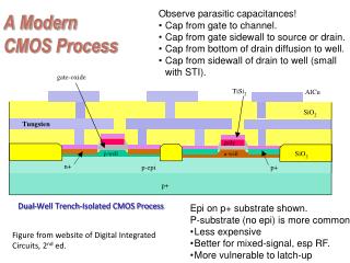
High barrier III-V FET with Self-Aligned Regrowth: Small Raccess Self-aligned High Velocity Channel Small Rc High mobility access regions Gate High-k n+ Regrowth Channel In(Ga)P Etch Stop High doping: 1013 cm-2 avoids source exhaustion 2D injection avoids source starvation Low sheet resistance; dopants active as-grown InAlAs Barrier Scalable III-V FET Design Classic III-V FET (details vary): { Large Area Contacts { Large Raccess Gap Source Drain Gate • Advantages of III-V’s Large Rc Top Barrier or Oxide { Channel • Disadvantages of III-V’s Bottom Barrier InAlAs Barrier Low doping M. Wistey, Spring ECS 2009
Regrown Contacts Metal Gate Source Contact High-k n+ Regrowth .... Channel Barrier Big Picture: Salicide-like Process Break from Silicon: No implantation Insufficient doping Surface damage Annealing is no panacea Encapsulate gate metals Arsenic capping Ship wafers for high-k Strain is cheap Analogy: Self-aligned silicide (salicide) process: Salicides Advantages: Self-aligned No e- barrier CMOS-safe metals Metal Gate High-k .... Salicide Channel Take from Silicon: Unlike classic III-V devices: Avoid liftoff Dry etches Self-aligned processes Surface channels Do III-V fabrication in Si-like fashion. M. Wistey, Spring ECS 2009
Channel Roughness Scattering • Challenge: Sixth power (!) scattering from interface roughness: • µ ~ (1/Mscat)2 ~ 1/(∂E/∂W)2 ~ W6(Gold SSC 1987) • Trend weaker in shallow or narrowwells (Li SST 2005) Fit: ~W-1.95 • Screening helps too • Does not seem to be a problem for 5nm InGaAs channels. M. Wistey, Spring ECS 2009
Drive Current in the Ballistic & Degenerate Limits where eot includes the electron wavefunction depth Inclusive of non-parabolic band effects, which increase cdos , InGaAs & InP have near-optimum mass for 0.4-1.0 nm EOT gate dielectrics Rodwell IPRM 2008
InAlAs mobility: 346 High Mobility in Narrow InGaAs Channels Hall Measurements No Shubnikov-de Haas Oscillations 4K • Electrons occupy multiple channels • But electrons aren’t in InAlAs...? • Unclear whether high mobility is in narrow channel • Unreasonable simulation difficulty. • Nonparabolic bands, degenerate statistics, bandgap renormalization, screening... • Need FET to remove uncertainty: eliminate doping altogether. M. Wistey, Spring ECS 2009
Regrowth Interface Resistances Interface resistances tested in separate blanket regrowths (no gates): In-situ Mo Contact ρc < 1 Ω - μm2 25 nm regrown InGaAs Rsh=70 Ω/sq Source Contact Drain Contact Metal Gate High-k n+ Regrowth InGaAs InP or InGaP etch stop InAlAs barrier InGaAs-InGaAs re-growth resistance < 1 Ω - μm2. InGaAs-InP re-growth resistance = 6 Ω - μm2 (on thick InP).
Critical etch process: Stop on channel with no damage Cr SiO2 Process Flow: Gate Deposition Metals e r • High-k first on pristine channel. • Tall gate stack. • Litho. • Selective etches to channel. NID InGaAs Channel InP/InGaP etch stop InAlAs barrier InP substrate M. Wistey, Spring ECS 2009
Gate Stack: Multiple Layers & Selective Etches Key: stop etch before reaching dielectric, then gentle low-power etch to stop on dielectric M. Wistey, Spring ECS 2009 Rodwell IPRM 2008
Process Flow: Sidewalls & Recess Etch SiO2, SiNx SiNx or SiO2 sidewalls Encapsulate gate metals Controlled recess etch Slow facet planes Not needed for depletion-mode FETs Metals e r Channel InP/InGaP etch stop InAlAs barrier InP substrate M. Wistey, Spring ECS 2009
Surface Preparation Before Regrowth SiO2, SiNx O3 (g) UV-ozone (20 min) HCl:H2O 1:10 etch (60 sec) H2O rinse, N2 dry Bake under ultrahigh vacuum Hydrogen cleaning 10-6 Torr, 30 min., 400°C (InP) or 420°C (InGaAs) Thermal deoxidation may work also. Metal e r Channel SiO2, SiNx HCl+H2O (l) Metal e r Channel SiO2, SiNx H2 + H (g) Metal e r Channel M. Wistey, Spring ECS 2009
Clean Surface Before Regrowth InP etch stop Clean, undamaged surface after Al2O3 dielectric etch & InGaAs recess etch. M. Wistey, Spring ECS 2009
At Last: Regrowth & Metal Regrow n++ InGaAs Doping: n~3.6x1019 cm-3 (Si~8x1019 cm-3) V/III ratio=30 Tsub = 460°C SiO2, SiNx Metals Mo e r n++ InGaAs n++ InGaAs Channel InP etch stop InAlAs barrier RHEED before growth Blanket metallization: Eitherin-situ Mo or ex-situ TiW Singisetti APL, submitted, or Crook APL 2007 M. Wistey, Spring ECS 2009
HAADF-STEM` Interface TEM of Regrowth: InGaAs on InGaAs 2 nm HRTEM InGaAs n+ regrowth Interface InGaAs n+ Regrowth on processed but unpatterned InGaAs. No extended defects. M. Wistey, Spring ECS 2009
Removing Excess Overgrowth 1. Spin on thick polymer Polymer Approach #1: Remove it Height-selective etch Wistey MBE 2008 & Burek JCG 2009 2. Mo & InGaAs Etch SiO2 SiO2 Polymer Metal Metal Oxide Oxide Regrowth Regrowth InGaAs InGaAs InGaP etch stop InGaP etch stop InAlAs barrier InAlAs barrier Approach #2: Don’t Grow It Quasi-Selective growth Wistey EMC 2009 M. Wistey, Spring ECS 2009
InP regrowth SEM InP regrowth RHEED Regrowth on InP vs. InGaP SEM: U. Singisetti InAs InAs InGaAs InAlAs barrier • Conversion of <6nm InP to InAs • Strain relaxation As P InGaAs InP etch stop InAlAs barrier As M. Wistey, Spring ECS 2009
Regrowth on InGaP As Converted from InGaP • Replace InP with InGaP • Converts to InGaAs (good!) • Strain compensation P InGaAs InGaAs InGaAs InGaP InGaP InGaP Wistey EMC 2008 InAlAs barrier InGaP regrowth SEM InGaP regrowth RHEED 2 M. Wistey, Spring ECS 2009
Scalable InGaAs MOSFETs 300 nm SiO2 Cap SiNx 50 nm Cr 50 nm W Mo Mo 5 nm Al2O3 n++ regrowth InGaAs Channel, NID n++ regrowth 3 nm InGaP Etch Stop, NID 10 nm InAlAs Setback, NID 5 nm InAlAs, Si=8x1019 cm-3 200 nm InAlAs buffer Semi-insulating InP Substrate Oblique view Top view SEM M. Wistey, Spring ECS 2009
0.9µm 0.8µm 0.7µm 0.6µm 0.5µm 0.5µm Scalable InGaAs MOSFETs 1µm 10µm 300 nm SiO2 Cap SiNx 50 nm Cr • Conservative doping design: • [Si] = 4x1013 cm-2 • Bulk n = 1x1013 cm-2 >> Dit • Large setback + high doping = Can’t turn off 50 nm W Mo Mo 5 nm Al2O3 n++ regrowth InGaAs Channel, NID n++ regrowth 3 nm InGaP Etch Stop, NID 10 nm InAlAs Setback, NID 5 nm InAlAs, Si=8x1019 cm-3 200 nm InAlAs buffer Semi-insulating InP Substrate M. Wistey, Spring ECS 2009
Series Resistance 300 nm SiO2 Cap Possible causes: Poly nucleation at gate Thinning near gate Strain-induced dislocations Incomplete underfill Insufficient doping under sidewall SiNx 50 nm Cr 50 nm W Mo 5 nm Al2O3 n++ regrowth InGaAs Channel, NID 3 nm InGaP Etch Stop, NID 10 nm InAlAs Setback, NID 5 nm InAlAs, Si=8x1019 cm-3 InAlAs buffer Now known to be a growth issue. See DRC & EMC 2009 for solution. M. Wistey, Spring ECS 2009
The Shape of Things to Come Generalized Self-Aligned Regrowth Designs: Recessed Raised Gate Gate Top Barrier Top Barrier n+ Regrowth Channel Channel Back Barrier Back Barrier Substrate Substrate • Self-aligned regrowth can also be used for: • GaN HEMTs (with Mishra group at UCSB) • GaAs pMOS FETs • InGaAs HBTs and HEMTs • All high speed III-V electronics M. Wistey, Spring ECS 2009
Conclusions • Scaled III-V CMOS requires more than reduced dimensions • InGaAs offers a high velocity channel, high mobility access • Self-aligned regrowth: a roadmap for scalable III-V FETs • Provides III-V’s with a salicide equivalent • Can improve GaN and GaAs FETs too • DFETs show peak gm = 0.24mS/µm • High resistance (a growth problem) limited FET performance M. Wistey, Spring ECS 2009
Acknowledgements • Rodwell & Gossard Groups (UCSB): Uttam Singisetti, Greg Burek, Ashish Baraskar, Vibhor Jain... • McIntyre Group (Stanford): Eunji Kim, Byungha Shin, Paul McIntyre • Stemmer Group (UCSB): Joël Cagnon, Susanne Stemmer • Palmstrøm Group (UCSB): Erdem Arkun, Chris Palmstrøm • SRC/GRC funding • UCSB Nanofab: Brian Thibeault, NSF M. Wistey, Spring ECS 2009
Conclusions • Scaled III-V CMOS requires more than reduced dimensions • InGaAs offers a high velocity channel, high mobility access • Self-aligned regrowth: a roadmap for scalable III-V FETs • Provides III-V’s with a salicide equivalent • Can improve GaN and GaAs FETs too • DFETs show peak gm = 0.24mS/µm • High resistance (a growth problem) limited FET performance M. Wistey, Spring ECS 2009