Download
1 / 85
850 likes | 1.07k Views
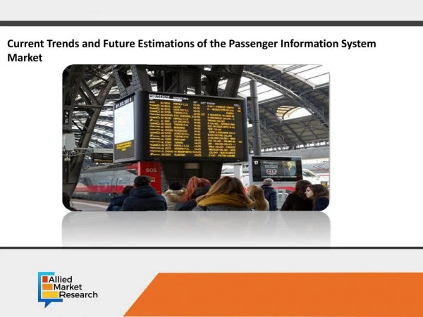
GJU Contract No.: GJU/06/2423/CTR/LMHC-TTCS. Freeflow tolling system Including passenger monitor system. Freeflow toll ing system with protection of personal data – including passenger monitoring system. The consortium is composed of four members:

E N D
GJU Contract No.: GJU/06/2423/CTR/LMHC-TTCS Freeflow tolling system Including passenger monitor system
Freeflow tolling system with protection of personal data – including passenger monitoring system • The consortium is composed of four members: • Logina d.o.o. is a SME from Slovenia that is the coordinator of the project. It is a producer of vehicle tracking systems and also has a control centre for controlling the network of Slovene Health terminals. • Moretti S.r.l. is a family owned SME from Italy. It works in the field of automation of public and private transit companies. It also supplies and installs AVM (Automatic Vehicles Monitoring). • Hamburg Consult GmbH is a SME from Germany. The company is active in the field of traffic management systems, which improve profitability and appeal of public transport. • The Traffic Technical Institute is part of the University of Ljubljana’s Faculty of Civil and Geodetic Engineering. They perform transportation planning, traffic control, safety and ecology, roadway design and geographic information systems.
Description of the Project & Summary of Objectives Presentation of the planned programme and the work undertaken Results of the design process and description of the system Tests and results Milestones Next steps and commercialization Main positive aspects Conclusions Agenda
1.1 Strategic background of the project • Ideas for the project: • The public’s ever increasing awareness that toll should be charged fairly, • Work on The Feasibility study on initiation of free flow electronic toll collection system in the Republic of Slovenia, • Reducing costs of toll collection, • Paying toll without stopping. • Major challenges: • Ensuring protection of personal data, • Fraud resistance, • Electronic toll payment. • Galileo: • Improved reliability and better accuracy only with GPS, • Use of an European system.
1.2 Description of the project • Create a freeflow toll charging system using EGNOS-enabled GNSS/GSM • Charge buses according to the number of passengers • Making a system that can make an analysis of road load • Making a system that can make an analysis of public transport
1.3 Objectives • The main objectives of the project were: • A prototype Control centre. • Prototype Toll meter or On board unit (OBU). • A system that can charge toll in relation to the number of passengers on the bus. • Electronic map of virtual toll stations. • Protected communication between the control centre and the OBU. • The end product is a system that allows anonymous toll collection without the drivers even having to stop. This should prevent most of the major traffic jams which occur when a larger mass of people is on the move, which happens before and after every major holiday, during the summer months, when major events are held,....
OBU Control centre GPS GALILEO IP Sec User account LCD monitor GSM GPRS GSM SIM passenger counter OBU SIM OBU procesor 1.4 System Overview
1.5 Project schedule Detailed description in deliverable D7.1
1.6 Project Budget Detailed description in deliverable D7.1
Description of the Project & Summary of Objectives Presentation of planned programme and the work undertaken Results of the design process and description system Tests and results Milestones Next steps and commercialization Main positive aspects Conclusions Agenda
2.1 Toll system basics • EXISTING TOLL SYSTEM • Closed toll system • paid by the distance traveled • both entry and exit toll stations • Open toll system • toll stations located on specific freeway cross-sections • paid by the price of cross-section passed through, • independently of either entry or exit point
2.2 Problem areas • Neighbouring traffic areas – EGNOS-enabledGNSS accuracy and logic related problems • other state roads, • municipal roads, • non-categorized roads, • forestry roads, • field roads, • parking spaces, • other traffic areas. • Impacts of engineering and other structures – EGNOS-enabled GNSSreliability related problems • overpass, • underpass, • tunnel, • cut, • tall buildings.
2.3 Guidelines for algorithm development • Respond correctly to technical limitations in a real environment (e.g. blackout ofthe GPRS and/orthe EGNOS-enabled GNSS signal). • Operate properly in the process of an increase of the number of users and toll stations. • Minimize system requirements. • Minimize communicational requirements. • Protect privacy. • Minimizethe human factor.
2.4 Basic algorithm • Has to enable the collection of the position of the vehicle. • If the vehicle crosses any of the virtual toll stations in the electronic map, then the Control centre has to be notified to charge toll.
2.5 Terminology • Virtual Toll Station • Is composed of one or several quadrilateral areas. • In this manner we produce larger adaptability in a real environment.
2.6 Terminology • Electronic map • It is the list of virtual toll stations that the OBU asks for. • The Electronic map is the key element of the system. • Limitations when designing the electronic map: • Memory capacity of the toll-meter (OBU) • The device is able to store only a part of the entire map. • Communication bandwidth between the OBU and the Control centre • There should be as little communication as possible.
2.7 The “Quadtree“ model • The idea behind quadtree is dynamic map partitioning based on toll station distribution. • A Cell is a rectangle with precisely defined geometrical position. • The sides of the cells are parallel with meridians and parallelsoflatitude. • The cell contains all the toll stations which (partially) lie inside the area, covered by the cell. • The Electronic map is a tree structure with individual vertices of cells. Detailed description in deliverable D3.5
2.8 Quadtree electronic map • The electronic map is built according to the following principles: • Electronic map can cover small region, whole EU or even whole world • The entire electronic map must be covered by a starting-point cell, which represents the root of the tree structure. • A maximum number of toll stations, which could be contained by individual cell, are defined. Otherwise the cell needs to be subdivided in four equal quadrants. • Newly emerged cells represent the leaves of the vertex of the subdivided cell. • The subdividing is recursively repeated until all the leaves contain the allowed number of stations. • Quadtree structure is very suitable for roaming Detailed description in deliverable D3.5
2.9 The “Quadtree” R0 R1.1 R1.2 R1.3.1 R1.3.2 R1.4 R1.3.3 R1.3.4 Detailed description in deliverable D3.5
Description of the Project & Summary of Objectives Presentation of planned programme and the work undertaken Results of the design process and description system Tests and results Milestones Next steps and commercialization Main positive aspects Conclusions Agenda
OBU Control centre GPS GALILEO IP Sec User account LCD monitor GSM GPRS GSM SIM passenger counter OBU SIM OBU procesor 3.1 System Overview
Cell zero OBU position is inside cell zero Is cell zero leaf of structure? Current OBU structure
Returned cell zero structure from Control Center OBU position is inside cell 3 Is cell 3 leaf of the structure? Current OBU structure
Returned cell 3 structure from Control Center OBU position is inside cell 3_4 Is cell 3_4 leaf of the structure? Control Center sends Stations data Current OBU structure
Leaf cell needs to be filled with stations data Current OBU structure
OBU is collecting and processing coordinates from EGNOS-enabled GNSS 3.6 Vehicle traveling the road
OBU is collecting and processing coordinates from EGNOS-enabled GNSS Vehicle traveling the road
Collected coordinate is inside station – crossing of station is detected Vehicle crosses station
Three more crossings are detected 3.9 Crossed stations
3.11 OBU - block diagram Detailed description in deliverables D2.2 and D4.1
3.13 OBU program modules GPS Manager Vehicle position GPRS Manager Encrypted communication between OBU and Control Centre Fills path trace Demand cell updates • OBU Manager • path trace • electronic map (part) Data updates FTP client Passenger counter Check path trace against electronic map IRMA User account id, keys SmartCard manager LCD manager User interface Detailed description in deliverables D3.2 and D4.2
3.14 Software platform • Operating system: Microsoft Windows CE 5.0 • Programming language: C++ • Development tool: Microsoft eMbedded Visual C++ 4.0 with CM_X255_INET_SDK • External libraries used: zlib 1.1.4, rsaeuro 1.04 • OBU main program has been developed as multithreaded Windows application: • Main program thread (OBUMainThread) • Thread for receiving GPS data and storing them into trace buffer (GPSThread) • Thread for checking smart card reader status and reading data from insertedcard (SmartCardThread) • Thread for data communication via GPRS modem (GPRSThread) • Thread for receiving passenger counter from IRMA device (IRMAThread)
3.15 OBU software • Communication: • Modified FTP. • Magic number – Session ID stored on SmartCard. • Encryption (public and private keys). • Commands in queue. • Cross calculation: • Get location from GALILEO/GPS module. • Confirm cell or download new cell. • Check location against cell data. • If location is inside any toll-station: • Generate crossed station command. • Put generated command in queue. Detailed description in deliverables D2.2 and D4.1
3.16 IRMA - Infra Red Motion Analyser Detailed description in deliverables D2.3 and D5.3
3.17 Purpose of Control Center • Processing OBU requests – communication, download of maps (99% of the time) • Configuring maps • Configuring cells. • Setting prices. • Managing accounts (creating, deleting, setting conto) • Planning and managing bus routes
3.18 Control Center schematics Detailed description in deliverables D2.1, D3.3, D3.5 and D4.2
3.19 Control centre database • All data are stored in the database LMHC-TTCS. • Main tables: • Stations, • Areas, • Prices, • Accounts. • Auxiliary tables: • Crossings, • Times, • Vehicle Categories, • Vehicles – Categories link table, • Buslines, • Buslines – Stations link table, • Cells, • Cells Coordinates, • Commands.
3.20 Communication with OBU Detailed description in deliverables D3.1, D3.3 and D4.2
3.21 Map management • Using GIS ArcView software • Data layers: • Aerial photographs, scale 1:5.000 • (source: Geodetic and Survey Authority, precision ± 3m) • State road network layer (precision ±3m) • Measurement using GPS (global positioning system) 3D Three-dimensional, transformed into 2D two-dimensional shape • Aerial photographs • Projections • State road network layer is updated annually Detailed description in deliverable D3.5
3.22 Map management • New station is defined • New area of station is defined using four coordinates • Optionally new areas are added to station • Price of station is defined • Deleting station • Deleting area • Checking differences between temporary map that we modify and map that OBUs are using • Station is added to database • Cell structure is callculated • Data can be used by OBU Detailed description in deliverable D3.5