Download
1 / 142
1.45k likes | 1.62k Views
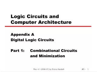
Logic Circuits and Computer Architecture. Appendix A Digital Logic Circuits Part 1: Combinational Circuits and Minimization. Discrete. Discrete. Information. Inputs. Discrete. Processing. Outputs. System. System State. Digital System.

E N D
Logic Circuits and Computer Architecture Appendix A Digital Logic Circuits Part 1: Combinational Circuits and Minimization RLAC (2008-09) by Luciano Gualà
Discrete Discrete Information Inputs Discrete Processing Outputs System System State Digital System • Takes a set of discrete information inputs and discrete internal information (system state) and generates a set of discrete information outputs RLAC (2008-09) by Luciano Gualà
Basic circuits • Combinational • without memory, stateless • Output = Function(Input) • Sequential • with memory, state dependent behaviour • State = Function (State, Input) • Output = Function (State) or Function (State, Input) • It can be: • Synchronous: state updated at discrete times • Asynchronous: State updated at any times RLAC (2008-09) by Luciano Gualà
Digital System Example: A B Combinational Circuit Inputs: Representation of A and B A + B Outputs: Representation of A+ B RLAC (2008-09) by Luciano Gualà
Digital System Example: A Digital Counter (e. g., odometer): Count Up 0 0 1 3 5 6 4 Reset Inputs: Count Up, Reset Outputs: Visual Display "Value" of stored digits State: RLAC (2008-09) by Luciano Gualà
Information Representation - Signals • Information variables represented by physical quantities (signals) • For digital systems, the variables take on discrete values • Two level, or binary values are the most prevalent values in digital systems • Binary values are represented abstractly by: • digits 0 and 1 • words (symbols) False (F) and True (T) • words (symbols) Low (L) and High (H) • and words On and Off • Binary values are represented by values or ranges of values of physical quantities RLAC (2008-09) by Luciano Gualà
Signal Example – Physical Quantity: Voltage Threshold Region RLAC (2008-09) by Luciano Gualà
Signal Examples Over Time Time Continuous in value & time Analog Digital Discrete in value & continuous in time Asynchronous Discrete in value & time Synchronous RLAC (2008-09) by Luciano Gualà
Binary Values: Other Physical Quantities • What are other physical quantities represent 0 and 1? • CPU • Disk • CD • Dynamic RAM voltage Magnetic Field Direction Surface Pits/Light Electrical Charge RLAC (2008-09) by Luciano Gualà
Information processing • by means of boolean gates • a boolean gate implements simple boolean operations (see later) • basic gates: • AND, OR, NOT • gates are used to build circuits RLAC (2008-09) by Luciano Gualà
Number Systems – Representation Positive radix, positional number systems • A number with radix ris rapresented by a string of digits: • A=an-1an-2…a1a0 .a-1,a-2,…,a-m • 0 ai < r • “.” is the radix point • Its (decimal) value is: RLAC (2008-09) by Luciano Gualà
Number Systems – Examples powers of radix RLAC (2008-09) by Luciano Gualà
Case r =2 • Let A=an-1an-2…a1a0 .a-1,a-2,…,a-m be a string of bits (binary digit) • Its (decimal) value is: Example: 1001.1011 = 23 + 20 +2-1 + 2-3 + 2-4 =9.6875 RLAC (2008-09) by Luciano Gualà
Decimal r =10 Binary r =2 Octal r =8 Hexadecimal r =16 00 01 02 03 04 05 06 07 10 11 12 13 14 15 16 17 0 1 2 3 4 5 6 7 8 9 A B C D E F 00 01 02 03 04 05 06 07 08 09 10 11 12 13 14 15 0000 0001 0010 0011 0100 0101 0110 0111 1000 1001 1010 1011 1100 1101 1110 1111 RLAC (2008-09) by Luciano Gualà
Decimal to binary conversion • Represent (111.6875)10 in pure binary Idea: • Convert the integer part into • Convert the fractional part into • Result: . RLAC (2008-09) by Luciano Gualà
Conversion of integer part • Represent (111)10 in pure binary • Repeat division by 2 111:2= 55 remainder 1 55:2= 27 remainder 1 27:2= 13 remainder 1 13:2= 6 remainder 1 6:2= 3 remainder 0 3:2= 1 remainder 1 1:2= 0 remainder 1 • RESULT: 1101111 • N.B.: Result bits are produced in reverse order Least Significant Bit (LSB) Most Significant Bit (MSB) RLAC (2008-09) by Luciano Gualà
Conversion of fractional part • Iterate multiplication taking the integer parts • Binary representation for 0.6875 ? 0.6875 x 2 = 1.375 take 1 0.375 x 2 = 0.75 take 0 0.750 x 2 = 1.5 take 1 0.5 x 2 = 1.0 take 1 • Result: 0.1011 • N.B.: Result bits here are produced MSB to LSB • the procedure sometimes does not converge • stop when the desired precision is reached MSB LSB (111.6875)10= (1101111.1011)2 RLAC (2008-09) by Luciano Gualà
Boolean Algebra • A useful mathematical system for specifying and transforming logic functions • We study Boolean algebra as a foundation for designing and analyzing digital systems! • Named from George Boole RLAC (2008-09) by Luciano Gualà
George Boole (1815-1864) An Investigation of the Laws of Thought, on Which are founded the Mathematical Theories of Logic and Probabilities (1854) RLAC (2008-09) by Luciano Gualà
Claude Shannon (1916-2001) A Symbolic Analysis of Relay and Switching Circuits (1938) ENIAC (Electronic Numerical Integrator And Calculator) (1946) RLAC (2008-09) by Luciano Gualà
Boolean Algebra • Boolean Algebra deals with • Binary variables take on one of two values. • Logical operators operate on binary values and binary variables • the two binary values have different names: • True/False • On/Off • Yes/No • 1/0 • Basic logical operators are the logic functions AND, OR and NOT RLAC (2008-09) by Luciano Gualà
Logical Operations • The three basic logical operations are: • AND , OR, NOT • AND is denoted by a dot (·). • OR is denoted by a plus (+). • NOT is denoted by an overbar ( ¯ ), a single quote mark (') after, or (~) before the variable • Intended meaning (for humans - Laws of Thought) • AND: both inputs are true • OR: at least one input is true • NOT: negate the input RLAC (2008-09) by Luciano Gualà
Notation Examples • Examples: • Y = AB is read “Y is equal to A AND B.” • z = x+y is read “z is equal to x OR y.” • X=A’ is read “X is equal to NOT A.” • Note: The statement: • 1 + 1 = 2 (read “one plus one equals two”) is not the same as • 1 + 1 = 1 (read “1 or 1 equals 1”). RLAC (2008-09) by Luciano Gualà
AND 0 · 0 = 0 0 · 1 = 0 NOT OR 1 · 0 = 0 1 + 1 = 1 0 + 0 = 0 = 0 1 1 · 1 = 1 0 + 1 = 1 = 1 0 1 + 0 = 1 Operator Definitions • Operations are defined on the values "0" and "1" for each operator: RLAC (2008-09) by Luciano Gualà
Boolean functions • Basic logical operators are the boolean functions f(x1,…,xn): {0,1}n {0,1} arguments domain codomain RLAC (2008-09) by Luciano Gualà
Formal definition of functions (1) • By means of “truth tables” • Explicit representation of the output for all possible combinations of values on its arguments RLAC (2008-09) by Luciano Gualà
…truth table for a 3-variable function… f(A,B,C)= 1 if and only if at least 2 variables are equal to 1 RLAC (2008-09) by Luciano Gualà
…number of rows of a truth table… • 1-variable function • 2 • 2-variable function • 4 • 3-variable function • 8 … • n-variable function • 2n RLAC (2008-09) by Luciano Gualà
Formal definition of functions (2) • By means of “boolean equation”: the function is specified as boolean expression of its arguments • boolean equation consists of: • variables • constants 0 and 1 • boolean operations (AND, OR, NOT) • parentheses M(A,B) = (((A)’(B)’) + (AB)) M = (((A)’(B)’) + (AB)) RLAC (2008-09) by Luciano Gualà
Boolean Operator Precedence • The order of evaluation in boolean expression is: • Parentheses • NOT • AND • OR • Consequence: parantheses appear around OR expressions • Example: F=A(B+C)(C+D’) M = (((A)’(B)’) + (AB)) M = A’B’ + AB RLAC (2008-09) by Luciano Gualà
From the boolean formula to truth table • Explicit case-by-case evaluation • Example: F = X + Y’Z RLAC (2008-09) by Luciano Gualà
Logic gates • A logic gate implements simple boolean operation • basic gates: • AND, OR, NOT • gates are used to build circuits RLAC (2008-09) by Luciano Gualà
NOT gate - the simplest one • NOT gate - inverts the signal If A is 0, X is 1 If A is 1, X is 0 • A NOT gate is also called an inverter RLAC (2008-09) by Luciano Gualà
AND gate • Output is 1 if all inputs are 1 • In general, if the AND gate has N inputs, input 1 AND input 2 AND … AND input N must be 1 for the output to be 1 • 2-input AND gate RLAC (2008-09) by Luciano Gualà
OR gate • Output is 1 if at least one input is 1 • In general, if the OR gate has N inputs, input 1 OR input 2 OR … OR input N must be 1 for the output to be 1 • 2-input OR gate RLAC (2008-09) by Luciano Gualà
A more complex example • 2-input “equivalence” circuit • The output is 1 if the inputs are the same • (i.e., both 0 or both 1) Truth table • Boolean function: M = A’B’ + AB RLAC (2008-09) by Luciano Gualà
Formal definition of functions (3) • By means of logic circuits • Combination of logic gates joined by wires RLAC (2008-09) by Luciano Gualà
Conventions for logic circuits RLAC (2008-09) by Luciano Gualà
From boolean formula to logic circuit • Idea: top-down or bottom-up construction • Example: write the logic circuit for F = X + Y’Z RLAC (2008-09) by Luciano Gualà
A more complex example • Exercise: bluid the logic circuit of the following function F = (A+BC)D + E RLAC (2008-09) by Luciano Gualà
From logic circuit to… • …truth table • explicit case-by-case computation • …boolean formula • left-to-right inspection RLAC (2008-09) by Luciano Gualà
Example • Write the boolean function and its truth table for the following logic circuit F =Y’+X’YZ’+XY X’YZ’ XY RLAC (2008-09) by Luciano Gualà
Function and Truth Table • F = Y’ + X’YZ’ + XY RLAC (2008-09) by Luciano Gualà
One more example… • Write the boolean function and its truth table for the following logic circuit X’ X’YZ X’YZ’ = Z’ X’YZ+X’YZ’+XZ XZ RLAC (2008-09) by Luciano Gualà
Function and Truth Table • F = X’YZ + X’YZ’ + XZ RLAC (2008-09) by Luciano Gualà
Conversion between representations • Circuit -> -> Boolean formula (left-to-right inspection) -> Truth table (explicit case-by-case computation) • Boolean formula -> -> Circuit (top-down/bottom-up construction) -> Truth table (explicit case-by-case evaluation) • Truth table -> -> Circuit (through boolean formula) -> Boolean formula (through canonical form – see later) RLAC (2008-09) by Luciano Gualà
duality principle: any algebraic equality remains true when the operators OR and AND, and the elements 0 and 1 are interchanged Boolean Identities 1A = A 0+A = A Identity 0A = 0 1+A = 1 Null AA = A A+A = A Idempotent AA’ = 0 A+A’ = 1 Inverse AB = BA A+B = B+A Commutative (AB)C = A(BC) (A+B)+C = A+(B+C) Associative A+BC = (A+B)(A+C) A(B+C) = AB+AC Distributive A(A+B) = A A+AB = A Absorption (AB)’ = A’+B’ (A+B)’ = A’B’ De Morgan RLAC (2008-09) by Luciano Gualà
Truth tables to verify De Morgan’s theorem RLAC (2008-09) by Luciano Gualà
Remark Each equality remains true if you sobstitute any variable with any expression Examples (A+B)(A+CD’) = A + BCD’ (distributive) ((A+BC)(D+A))’ = (A+BC)’ + (D+A)’ (De Morgan) = A’ (BC)’ + D’A’ (De Morgan) = A’(B’+C’) + D’A’ RLAC (2008-09) by Luciano Gualà
Generalized De Morgan’s theorems X1+X2+…+Xn = X1 X2 … Xn X1 X2… Xn = X1+X2+…+Xn RLAC (2008-09) by Luciano Gualà