Download
1 / 18
190 likes | 355 Views
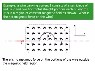
Magnetic survey of the CESR interaction region quadrupole magnets using vibrating wire technique. Alexander Temnykh and Scott Chapman Cornell University, Ithaca, NY 14850, USA. BNL NSLS, 6/1/06. Content. Introduction Setup Magnetic survey and alignment Permanent quadrupole magnets

E N D
Magnetic survey of the CESR interaction region quadrupole magnets using vibrating wire technique. Alexander Temnykh and Scott Chapman Cornell University, Ithaca, NY 14850, USA BNL NSLS, 6/1/06
Content • Introduction • Setup • Magnetic survey and alignment • Permanent quadrupole magnets • Super – conducting quadrupoles • Summary and Conclusion A. Temnykh, BNL NSLS, 6/1/06
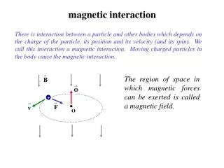
Introduction (basic) Vibrating wire setup is a stretched wire with AC current with natural wire vibrating frequencies. Standing wave amplitude and phase will depend on the location of the magnetic field. AC current with resonance frequency Lorenz forces No excitation if the field in the node of standing wave. Maximum excitation if the field location at maximum standing wave amplitude A. Temnykh, BNL NSLS, 6/1/06
Introduction (advanced) • Equation for the string motion driving by AC current: • Solution - sum of standing waves A. Temnykh, Vibrating wire field-measuringtechnique, Nuc. Inst., A 399 (1997) 185-194 • Measuring xn one can find Bn and reconstruct B(z) !!! A. Temnykh, BNL NSLS, 6/1/06
CESR final focusing quadrupole magnets survey /alignment setup Wire geometry: SC SC PM Q0E/W – permanent quadrupole magnets Q1E/W and Q2E/W super-conducting quadrupole magnets in cryostats (1) – 7.536m long 0.1mm copper-beryllium wire (2) – precise moving stages with optical targets. (3) – constant tension mechanism. (4) – wire motion sensors A. Temnykh, BNL NSLS, 6/1/06
Q0W Q0E Permanent magnets survey (analysis example) Reconstructed horizontal magnetic field, Bx(z) Vertical standing wave amplitudes Wire vertical position at Q0E,W Y = 0.039mm Y = -0.061mm dy = - 0.1mm differential effect Q0E Q0W A. Temnykh, BNL NSLS, 6/1/06
Q0E Q0E Q0E Q0E Q0W Q0W Q0W Q0W Permanent magnets survey(all SC quads turned off) Vertical position survey Horizontal position survey ywire = -0.061mm xw = 0.07mm dywire = 0.1mm effect dxw = 0.1mm effect PM quads vertical position: Q0E -0.20mm, Q0W 0.11mm PM quads horizontal position: Q0E -0.14mm, Q0W 0.11mm A. Temnykh, BNL NSLS, 6/1/06
Q1E, vertical Q1E, horizontal 1) I(Q1W) = 243A Y = -0.159 +- 0.013mm 2) I(Q1W) = 465A Y = -0.169 +- 0.018mm 1) I(Q1E) = 231A y = 0.142 +- 0.007mm 2) I(Q1E) = 466A y = 0.141 +- 0.010mm 1) I(Q1W) = 233A x = -0.019 +- 0.001mm 2) I(Q1W) = 466A x = -0.022 +- 0.002mm 1) I(Q1E) = 231A x = -0.010 +- 0.004mm 2) I(Q1E) = 466A x = -0.002 +- 0.001mm Super-conducting magnets survey For Q1E & Q1W survey the 4th order standing wave has been used. Surveyed magnets Q1W, vertical survey Q1W, horizontal A. Temnykh, BNL NSLS, 6/1/06
Vertical Horizontal Horizontal Vertical 1) I(Q2W) = 183A x = -0.033 +- 0.001mm 2) I(Q2W) = 366A x = -0.029 +- 0.001mm 1) I(Q2W) = 183A Y = 0.006 +- 0.017mm 2) I(Q2W) = 366A Y = -0.001 +- 0.021mm 1) I(Q2E) = 180A x = -0.006 +- 0.002mm 2) I(Q2E) = 360A x = -0.001 +- 0.001mm 1) I(Q2E) = 180A y = 0.109 +- 0.007mm 2) I(Q2E) = 360A y = 0.119 +- 0.003mm Super-conducting magnets survey For Q2E & Q2W survey the 6th order standing wave has been used. Surveyed magnets Standing wave amplitude with sign versus string position Q2W magnetic survey Q2E magnetic survey A. Temnykh, BNL NSLS, 6/1/06
Magnetic Survey summary Over all survey precision ~ 0.07mm ~0.050 mm from wire ends position optical survey ~0.010 mm from magnetic survey A. Temnykh, BNL NSLS, 6/1/06
“Standard” bar Solenoid still yoke wire Optical wire position sensor mounted on platform Transferring of the wire position to outside world (resent development). Precise moving platform • Wire position sensor signal as function of platform position. • Wire is free • Wire is pressed against the “standard” bar • Touch point. (2) (1) (3) A. Temnykh, BNL NSLS, 6/1/06
Pulsed to VW setup conversion (sensitivity study) Sensitivity ~ 0.2Gcm ! A. Temnykh, BNL NSLS, 6/1/06
VW using for sextupole magnet alignment Sextupole magnet example: 10cm long, 30mm bore radius 1.5T field on pole tip Sextupole center from quadratic fit: X = 0.0018 +- 0.0013mm A. Temnykh, BNL NSLS, 6/1/06
Conclusion • WV technique has been used for magnetic survey of permanent and super-conducting quadrupole magnets of IR of Cornell Electron Storage Ring (CESR). The survey has been done in situ with CLEO detector field turned ON. • The technique demonstrated ~0.010mm or better precision in the finding of the quadrupole magnet magnetic centers. • The factors limiting the overall survey precision are: • Optical survey of the wire ends ~ 0.050mm • Stages motion ~ 0.010mm • Both can be improved. • Note: fundamental mode frequency variation df/f ~ 5x10⁻⁴ produces the sag error ~0.002mm. A. Temnykh, BNL NSLS, 6/1/06
Vibrating Wire Sensitivity Testat NSLS Alexander Temnykh1 and George Rakowsky, Dave Harder & Mike Lehecka June 1, 2006 1Cornell University
NSLS Pulsed Wire Bench Converted to Vibrating Wirefor Sensitivity Study PHOTO-OPTICAL WIRE POSITION DETECTORS (X & Y) CALIBRATED P-M DIPOLE (100 G-cm) E-M DIPOLE (VARIABLE) X-Y-Z STAGE X-Y-Z STAGES 125 µm BeCu WIRE AUDIO OSCILLATOR ~56 Hz 2nd Harmonic Vibration Mode ~1kg SCOPE PC ~1.5m 1.4m 5.1m Method: • Vary EM current to cancel PM dipole kick. • Measure wire vibration amplitude vs. current A. Temnykh, BNL NSLS, 6/1/06
Vibrating Wire Sensitivity Study Sensitivity ~ 0.2Gcm ! A. Temnykh, BNL NSLS, 6/1/06
Using VW for Sextupole Magnet Alignment Sextupole magnet example: 10cm long, 30mm bore radius 1.5T field on pole tip Sextupole center from quadratic fit: X = 0.0018 +- 0.0013mm A. Temnykh, BNL NSLS, 6/1/06