Download
1 / 114
1.14k likes | 1.15k Views
Chapter 6 Excavation-Grading and Compacted Fill Compaction. Prepared From The Coduto’s Text Book by Instr. Nurullah AKBULUT.

E N D
Chapter 6Excavation-Grading and Compacted FillCompaction Prepared From The Coduto’s Text Book by Instr. Nurullah AKBULUT
Most civil engineering projects include some earthwork, which is the process of changingthe configuration of the ground surface. When soil or rock is removed, we have made a cutor excavation; when it is added, we have made a fill or embankment. • Earthwork also is important in building construction, especially in hilly terrain. Cuts and fills are used to create level pads for the buildings, parking lots, and related areas,thus using the land area to better advantage. • Even building projectsin areas with naturally level terrain often require minor earthwork to provide proper surfacedrainage. • Finally, the most impressive earthwork projects are earth dams. They require very large volumes of carefully placed fill, yet are much lessexpensive than concrete dams because such fills can be placed very economically. Whenproperly designed and constructed, earth dams also are very safe.
Figure 6.2 Typical cross-section through a proposed building site showing locations of proposed cuts and fills.
Figure 6.3 Oroville Dam on the Feather River in a California. This is a 225 m (740ft) tall earth dam with a volume of 61,000,000 m3 (80,000,000 yd3) (California Department of Water Resources)
EARTHWORK CONSTRUCTION OBJECTIVES • The most fundamental objective of earthwork construction is to change the ground surfacefrom some initial configuration, typically described by a topographic map, to some finalconfiguration, as described on a new topographic map known as a grading plan. Thesechanges are often necessary to properly accommodate the proposed construction, and tomaintain proper surface drainage, which is important to the long-term performance of cutsand fills. • Another important requirement is that earthwork must not create slope stability problems (i.e., landslides). This is especially important in hilly and mountains areas, since the level building pads or road alignments created by the earthwork are possible onlybecause nearby areas are made steeper and thus less stable.
Compacted fills have additional requirements, including: 1)Fills must have sufficient shear strength to support both their own weight and externalloads, such as foundations or vehicles. Lack of sufficient strength can produce landslides, bearing capacity failures, and rutting of pavements. 2)Fillsmustbesufficientlystifftoavoidexcessivesettlement. Soft fillspermitfoundationstosettleexcessivelythusdamagingbuildings,andoftenproduceundesirablechangesin surface drainage patterns. 3) Fills must continue to satisfy requirements 1and 2, even if they become wet. 4)Some fills,such as the core of earth dams or liners for sanitary landfills, must have a sufficiently low hydraulic conductivity to restrict the flow of water. Others,such asaggregate base material below pavements,must haveahighhydraulicconductivitytodrain water away from critical areas. 5)In areasprone to frostheave(a heaving that occurs when the groundfreezes),itissometimes desirable to havefills made ofsoilsthatarenot frost-susceptible
CONSTRUCTION METHODS AND EQUIPMENT Figure 6.4 Construction of the Culebra Cut for the Panama Canal, 1907. The steam –powered excavators placed loads of soil and rock into railroad cars that hauled them away (Library ofCongress).
Historic Methods The first significant advancements came in the nineteenth century with the introduction of steam power. This lead to mechanized earthmoving equipment and began the era of efficient large-scale earthmoving. Steam-powered equipment was used to build the Panama Canal, which was the largest earthmoving project of its day. The Culebra Cut (now known as theGaillard Cut). Shown in Figure 6.4, was the most difficult part of the construction due to is height and the very difficult geologic conditions. The Cat passes through a formation known as the Cucaracha (Cockroach) shale, a weak sedimentary rock. Unfortunately, the first efforts to build the canal were orchestrated by the arrogant Ferdinand de Lesseps, who despised engineers and began construction without the benefit of a geologic study (Kerisel,1987). This lead to a misguided attempt to build a see-level canal, which would have required a 109 m.cut atCulebra. massive land slides (created by the construction activities),yellow fever, and financial insolvency eventually halted the first attempt to build the canal. Whenconstructionresumed with the benefit of geologic studies,locks had been addedtoraisethecanal 25 m above sea level. Even so, huge landslides continued tobe a problem, resulting in enormous excavation quantities. TheCulebra Cutalonerequired 75.000.000m3 (98,000,000 yd3), a massivequantity even by today’sstandards.The canal wascompleted in 1914, and stands as both a great civilengineering achievement and a dramaticcase studydemonstrating theimportance of geology.
Hydraulic Fills During the early decades of the twentieth century,many large earthwork projects were builtusing a technique called hydraulic filling. This method consisted of mixing the soil withlarge quantities of water , conveying the mixture to the construction site though pipes andflumes, then depositing it at the desired locations. The soil settled in place and the excesswater was directed away. Nocompaction equipment was used. Figure 6.5 shows a hydraulic fill dam under construction. This technique was popular between 1900 and 1940, especially for earth fill dams, because earthmoving equipment was too small and underpowered for such large projects.Unfortunately , the quality of such fills was poor and they often experienced largesettlements and landslides. The last significant hydraulic fill in the United States was at Ft. Peek Dam in Montana. A very large, 3.800.000 m3 (5.000.000 yd3) landslide occurred during construction in 1938. it was blamed on the poor quality of the hydraulic fill. The adventof modern earthmoving equipment was already underway, making hydraulic fills obsolete. Another serious problem with hydraulic fills became evident in 1971 when the LowerSan Fernando Dam near Los-Angeles failed during a magnitude 6.4 earthquake. This failure was due to liquefaction of the hydraulic fill soils. As a result, several hydraulic fill dams have been rebuild or replacedto avoid similar failures.
Figure 6.5 Construction ofSan Pablo Dam in California using by hydraulic filltechniques, circa 1918. Two fills are being placed simultaneously, one on each side of photograph, tofrom the shells. The finersoils flow to the center andfrom the impervious core. (US Bureau of Reclamation)
Modern Earthmoving Equipment • a) Track-mounted or crawler type; b) Wheel-mounted type.( caterpillar Inc.) • Figure 6.6 Tractors
Figure 6.7 Wheel-mounted loader removing soil from a stockpile. (Caterpillar inc.)
Figure 6.8 A backhoe is atractor with a loader on thefront and a hoe an the back. They are commonly used todig trenches, as shown here. (Caterpillar inc.)
Figure 6.9 An excavator is a large hoe mounted on a special rotating chassis. The excavator is digging a hole on the right side of the picture and dumping the spoils in a pile on the left side. Excavators also can dump directly into trucks. (Caterpillar Inc.)
Conventional Earthwork • We will use the term conventional earthwork to describe the excavation. transport, placement, and compaction of soil or soft rock in areas where equipment can move freely.This process may be divided into several distinct steps, each requiring appropriateequipment and techniques.
Clearing and Grubbing • The first step in most earthwork projects is to remove vegetation, trash, debris, and otherundesirable materials form the areas to be cut or filled. Stumps, roots, buried objects, andcontaminated soils also need to be removed. Most of these materials would have adetrimental effect on the fill, and must be hauled off the site. The above-ground portion ofthis work, as shown in Figure 6.10, is called clearing and the underground portion is calledgrubbing. • Sometimes clearing are and grubbing is accompanied bystripping, which consistsremoving and storing the topsoil. Such soils are valuable because they contain nutrients forplants. Once the grading is completed, these soils are returned to the top of thegraded surface in areas to be landscaped. • Limited quantities of inorganic debris, such as chunks of concrete, bricks, or asphaltpavement, do not need to be hauled away and may be incorporated into the fill so long asthey are no larger than about 250mm (10 in). Those larger than about 100mm (4 in)in diameter are called oversize ,and must not be spread out in the fill, because stacking them in one place would leave undesirable voids. In addition, oversized objects must not be placed in fills that are to be penetrated with pile foundations, nor in upper 3 m(10 ft), as they would cause problems with utility excavations
Figure 6.10 Clearing and grubbing in a former orange grove. The trees are being removed and hauled to the dumpster seen in the background.
Excavation • Excavation which is the removing of soil or rock, can occur at many different locations. Usually ,most of the excavation occurs in areas where the proposed ground surface is lowerthan the existing ground surface. Normally these excavated materials are then used to make fills at other portions of the project site. Sometimes additional soil is needed, so it becomes necessary to obtain it by excavating at offsite borrow pits, which are places where soil is removed to be used as import (the term “borrow” is a misnomer, since we have no intention of bringing the soil back!). Finally, areas to be filled are often prepared by first excavating loose upper soils, thus exposing firm ground on which to place the fill.
Figure 6.11 A scraper transporting a load of soil across a construction site.This scraper is a equipped with an elevating mechanism at the front of the bowl to assist in loading soil.
Figure 6.12 Operation of it scraper: a) To bad the bowl, the operator opens the apron, moves the ejector plate to the rear, and lowers the front so it digs 100—150mm (4—6 in) into the ground. As the scraper moves forward, it fills with soil. In a harder ground, it may be necessary to push the scraper with a bulldozer during the boarding phase. b) To transport soil, the apron is closed and the bowl is lifted. Scrapers usually transport soil at speeds of about 32 km/hr (20 mi/hr). c) Upon reaching the area to be filled, the operator again opens the apron, but lowers the bowl only slightly, leaving it 100—150 mm (4—6 in) above the ground surface. The ejector is moved forward, pushing the soil out and under the bowl, thus depositing a uniform thickness of soil (Wood, 1977).
Sometimes the ground is too hard to be excavated with a scraper or loader. This problem often can be overcome by first loosening it with a ripper attached to a tractor, as shown in Figure 6.13. This device consist of one or more teeth that are pressed into the ground, then pulledthrough to loosen it. The ripping operation can then be followed byexcavating equipment. Figure 6.13 A truck-mounted tractor equipped with a ripper. This ripper has two teeth, others have as many as four or five, depending on the type of ground to be ripped ant the power of the tractor. The teeth are hydraulically lowered into the ground, then pulled by the tractor.
Often the excavatability (ease of excavation) or rippability (ease of ripping) at a site is evident from a visual inspection, and the proper equipment andtechniques may be selected accordingly atquestionable sites, measurements of the seismic wave velocity from a seismic refraction survey can assist in selecting the properequipment. Generally, soil and rock with velocities less than about 500 m/s (1600 ft/s) canbe excavated without ripping. Higher velocities can be assessed using Figure 6.14. • Rippability also depends on other factors not reflected in the seismic wave velocity,such as the size and spacing of joints, ripper tooth penetration, presence of boulders, andoperator technique.
Figure 6.14 Ripping capabilities of a Caterpillar D9N TRACTOR WİTH A No.9 ripper bar (Caterpillar, 1993). Conditions identified as “non-rippble” generally require blasting.
Transport and Placement • Although bulldozers and wheel loaders can transport soils for short distances (i.e.. less than100-150 m), they become very uneconomical with longer hauls. For these projects, it becomes necessary to use other equipment. • Scrapes are very efficient at moderate- length hauls, and money earthwork projects fallinto this category. They can excavate, transport, and place the soil, asdescribed above, but cannot be used to haul over public highways. • Dump trucks can be used instead of scrapers, especially when the soil is beingexcavated by loaders as shown in Figure 6.15. Most dump trucks can travel over publichighways, and they move faster then scrapes. However, this methodrequires moreequipment and more operators.
Figure 6.15 A large dump track. This one is too large to travel on high ways, and is used only when all of its movement can occur off road. Smaller dump tracks also are available, and they can travel on highways. (Caterpillar Inc.)
Figure 6.16 A very large off-road wagon. Upon reaching its definition, this wagon will unload the soil through doors on the bottom. Smaller versions of this design can be towed by semi tractors over the highways.
TABLE 6.1 ECONOMICAL HAUL DISTANCES (Adapted from Caterpillar, 1993)
Moisture Conditioning • The soil must be at the proper moisture content before it is compacted. Soils that are toowet or too dry will not compact well. Usually the moisture content is not correct and needsto be adjusted accordingly. If the soil is too dry, this is usually done by spraying it with a water truck, as shown in Figure 6.18. A bulldozer or other equipment is then used to mix the soil so the water is uniformly distributed • The grading contractor has a much more difficult problem when the soil is too wet.Mixing it with dryer soil is difficult, especially with clays, because it is very hard to achievethorough mixing. The result often consist of alternating clumps of wet and dry soil insteadof a smooth mixture. The most common technique is to spread the wet soil over a large areaand allow the sun to dry it. This works well so long as a rainstorm does not occur!
Figure 6.18 A water truck spraying a new lift of soil for a fill and preparing it to be compacted.
Compaction • Compaction is the use of equipment to compress soil into a smaller volume, thus increasing its dry unit weight and improving its engineeringproperties. • The solids and water are virtuallyincompressible, so compaction produces areduction in the volume of air
Figure 6.19 Three phase diagrams showing the changes in soil as it moves from its naturel location to a compacted fill.
Compaction Equipments • Differences between compaction equipment and the other excavation equipment: • Most construction equipment is intentionally designed to have low contact pressures between the tires or tracks and the soil. This allows them to travel more quickly andeasily through soft ground. For example. A Caterpillar 973 track loader has a contactpressure of only 83 kPa. Such pressures are too low to produce the required compaction in normal-thickness lifts. • Incidental traffic usually follows common routes, so their compactive effort is notuniformly distributed across the fill. Thus, some areas may receive sufficientcompaction, while others receive virtually none.
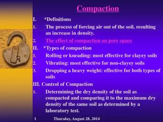
All compaction equipment uses one or more of the following four methods (Spann, 1986): • Pressure--- The contact pressure between the equipment and the ground is probably the most important factor in the resulting compaction of the underlying soils. A typical sheepsfoot roller has a contact pressure of about 3500 kPa (500 lb/in2), which is far greater than the track-mountedequipment described earlier. • Impact---Some equipment imparts a series of blows to the soil, such as by dropping a weight. This adds a dynamic component to the comp active effort. • Vibration--- Vibratory compaction equipment utilizes eccentricweights or some other device to induce strong vibration into the soil, which can enhance its compaction . These vibrations typically have a frequency of 1000—3500 cycles perminute. • Manipulation--- Compaction equipment that imparts some shearing forces to the soilcan also contribute to better compaction. This action is called kneadingormanipulation. However excessive manipulation, such as in anoverly wet fill, can be detrimental. When such fills are simply being moved around with no compaction occurring , we have a condition called pumping.
The proper selection of compaction equipment and methods depends on the type of soil, the size of the project compaction requirements required production and other factors. No single device is the best choice for all situations. Figure 6.20 shows typical ranges of soil types for various types of compactors.
Figure 6.20 Soil types best suited for various kinds of compaction equipment (Adapted from Caterpillar,1993).
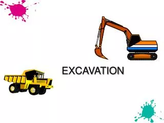
Sheepsfoot roller • Sheepsfoot rollers compact soil by pressure and manipulation. They can be used on a variety of soils, but work best in silts and clays. Most sheepsfoot rollers can accommodate soil lifts with loose thicknesses of about 200 mm(8 in). Tamping foot rollers Tamping foot rollers are very similar to sheep foot rollers, except they use larger feet with acorrespondingly smaller contact pressure. They can be operated at a faster speed,. But do not compact to as great a depth.
Figure 6.21 Sheepsfoot rollers: b)Self-propolled roller. (Caterpillar Inc.)
Sheepsfoot rollers • Has many round or rectangular shaped protrusions or “feet” attached to a steel drum • 8% ~ 12 % coverage • Contact pressure is from 1400 to 7000 kPa • It is best suited for clayed soils. • Compactive effort: static weight and kneading.
Tamping foot roller • About 40% coverage • Contact pressure is from 1400 to 8400 kPa • It is best for compacting fine-grained soils (silt and clay). • Compactive effort: static weight and kneading.
Pneumatic rollers Pneumatic rollers (also known as rubber-tire rollers) are heavy units resting onseveral tires. The contact pressure is typically about 600 kPa (85 1b/in). Each tire is able to move up and down independently, so this device is good at finding small soft spots that rigid compaction equipment, such as sheep foot rollers, can miss. The tires also provide a kneading action that enhances compaction. These rollers can compact lifts with loose thicknesses of 250—300 mm (10—12 in).
Pneumatic (or rubber-tired) roller • 80% coverage under the wheel • Contact pressure up to 700 kPa • Can be used for both granular and fine-grained soils. • Compactive effort: static weight and kneading. • Can be used for highway fills or earth dam construction.
Vibratory rollers • Vibratory rollers, such as the one in Figure 6.22, are similar to sheep foot or tamping foot rollers with the addition of a vibrating mechanism. Thus, they use pressure manipulation, and vibration to compact the soil. Vibration is especially effective in sandy and gravelly soils. The heaviest of these rollers can accommodate loose lift thicknesses of up to 1 m (3 ft), and they provide some compactive effort to depths of about 2 m (7 ft)
Smooth steel-wheel rollers • Smooth steel-wheel rollers (don’t call them “steamroller”), such as the one in Figure 6.23, leave a smooth compacted soil surface. The non-vibratory types are not well suited for compacting soil because the contact pressure is much lower than that of sheepsfoot rollers. However, they may be used to proof roll a subgrade just before paving (i.e., a final rolling to confirm compaction of the upper most soils), and to compact the aggregate base course and asphalt pavement.
Figure 6.23 A smooth steel- wheel roller preparing to compact an asphalt pavement.(Caterpillar Inc.)
Smooth-wheel roller (drum) • 100% coverage under the wheel • Contact pressure up to 380 kPa • Can be used on all soil types except for rocky soils. • Compactive effort: static weight • The most common use of large smooth wheel rollers is for proof-rolling subgrades and compacting asphalt pavement.
Vibrating drum on smooth-wheel roller • Vertical vibrator attached to smooth wheel rollers. • The best explanation of why roller vibration causes densification of granular soils is that particle rearrangement occurs due to cyclic deformation of the soil produced by the oscillations of the roller. • Compactive effort: static weight and vibration. • Suitable for granular soils
Mesh (or grid pattern) roller • 50% coverage • Contact pressure is from 1400 to 6200 kPa • It is ideally suited for compacting rocky soils, gravels, and sands. With high towing speed, the material is vibrated, crushed, and impacted. • Compactive effort: static weight and vibration. Holtz and Kovacs, 1981
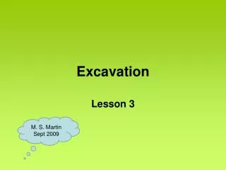
Elephant and Compaction Question? The compaction result is not good. Why? He He! I’m smart. Heavy Weight