Download
1 / 89

E N D
UNIT I SYNCHRONOUS GENERATOR Constructional details – Types of rotors – EMF equation – Synchronous reactance – Armature reaction – Voltage regulation: EMF, MMF, ZPF and ASA methods – Synchronizing and parallel operation – Synchronizing torque – Change of excitation and mechanical input – Two reaction theory – Determination of direct and quadrature axis synchronous reactance using slip test – Operating characteristics – Capability curves.
UNIT II SYNCHRONOUS MOTOR Principle of operation – Torque equation – Synchronizing to infinite bus bars – Operating characteristics – Methods of Starting – Phasor diagrams – V curves and Inverted V curves – Power angle characteristics – Synchronous condensers – Hunting, damper windings, applications –brushless DC motors.
UNIT III THREE PHASE INDUCTION MOTOR Constructional details – Types of rotors – Principle of operation – Slip – Equivalent circuit – Slip –torque characteristics – Condition for maximum torque – Losses and efficiency – Load test – No load and blocked rotor tests – Circle diagram – Separation of no load losses – crawling – cogging – Double cage motor – Induction generator.
UNIT IV STARTING AND SPEED CONTROL OF THREE PHASE INDUCTION MOTOR Methods of starting: DOL starter, Stator resistance starter, Auto Transformer starter, rotor resistance starter and star–delta starter – Methods of Speed control: speed control by change of frequency, speed control by number of poles and speed control by change of slip.
UNIT V SINGLE PHASE INDUCTION MOTORS AND SPECIAL MACHINES Constructional details of single phase induction motor – Double field revolving theory – Equivalent circuit – types of single phase Induction motor – Special machines: Reluctance motor, Switched Reluctance motor, Repulsion motor, hysteresis motor, stepper motor, DC Servo motor, AC servomotor and Universal motor.
TEXT BOOKS: Theraja. B.L., Theraja.A.K. “A Textbook of Electrical Technology, Volume II (AC & DC Machines)”, S.Chand& Company Ltd.,2008. Murugesh Kumar, K, “Induction & Synchronous Machines”, Vikas publishing house Pvt.Ltd., 2000. REFERENCES: Gupta.J.B., “Theory and Performance of Electrical Machines”, S.K. Kataria and Sons, 2002. Kothari. D.P. and Nagrath. I.J., “Electric Machines”, Tata McGraw Hill Publishing Company Ltd, 2002. Fitzgerald. A.E., Charles Kingsley, Stephen.D.Umans, “Electric Machinery”, Tata McGraw Hill publishing Company Ltd, 2003.
UNIT – I SYNCHRONOUS GENERATOR AC Machines Synchronous Machines Asynchronous Machines (Induction Machine) Induction Generator Induction Motor Synchronous Generator Synchronous Motor Due to lack of a separate field excitation, these machines are rarely used as generators. Most widely used electrical motors in both domestic and industrial applications Used as motors as well as power factor compensators (synchronous condensers) A primary source of electrical energy
SYNCHRONOUS GENERATOR Types of Synchronous Machine According to the arrangement of the field and armature windings, synchronous machines may be classified as • Stationary Armature - Rotating Field (Above 5 kVA) • (b) Stationary Field – Rotating Armature (Below 5 kVA)
Advantages of stationary armature - rotating field: • The High Voltage ac winding and its insulation not subjected to centrifugal forces.(11kV - 33 kV) (BETTER INSULATION) • Easier to collect large currents from a stationary member. • Rotating field makes overall construction simple. • Problem of sparking at the slip ring can be avoided. • Ventilation arrangement for HV can be Improved. • The LV(110 V – 220V) dc excitation easily supplied through slip rings and brushes to the rotor field winding. • Noiseless running is possible. • Air gap length is uniform • Better mechanical balancing of rotor
CONSTRUCTION OF ALTERNATOR Stationary Armature - Rotating Field An alternator has 3 phase winding on the stator and DC field winding on the rotor. STATOR Stationary part of the machine. It is built up of Sheet-Steel Lamination Core (Stampings) with slots to hold the armature Conductor Armature winding is connected in STAR
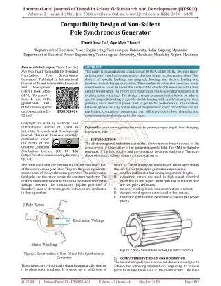
ROTOR: There are two types of rotor i) Salient Pole type {Projected Poles} ii) Non - Salient Pole type {Non – Projected Poles} Smooth Cylindrical Type
Salient Pole type {Projected Poles} It is also called Projected Poles. Poles are mounted on the larger circular frame. Made up of Thick Steel Laminations. Field Winding are connected in series. Ends of the field winding are connected to the DC Supply through Slip Rings Features Large Diameter and short Axial Length. Poles are Laminated to reduced Eddy Current Losses Employed for Low and Medium Speed 120 RMP to 500 RPM (Diesel & Hydraulic Turbines) This cannot be used for Large speed
DAMPER WINDING Pole faces are provided with damper winding Damper winding is useful in preventing Hunting EMF generated will be sinusoidal Copper Bar
II) NON SALIENT POLE TYPE Smooth cylindrical rotor or TURBO ALTERNATOR field winding used in high speed alternators driven by steam turbines . Features Smaller diameter and larger axial length compared to salient pole type machines, of the same rating. Less Windage loss. Speed 1200 RPM to 3000 RPM.. Better Balancing.. Noiseless Operation Flux distribution nearly sine wave Frequency 50 Hz Ns = 120 F / P
EMF Equation Where,K c = cos (α/ 2), K d = {sin (mβ/ 2)} / {m sin (β/ 2)} f = PNs/120, Hz; Φ = flux per pole, Wb T ph = Turns in series per phase = ( No. of slots * No. of cond. per slot) / (2 x 3) phd c ph T f K K E 44.4 EMF Equation of an Alternator Let Φ= Flux per pole, Wb P = Number of Poles Ns = Synchronous Speed in RMP Z = Total Number of Conductors or coil sides in series / Phase Z = 2T T = Number of coils or Turns per phase Tph = Turns in series per phase = ( No. of slots * No. of cond. per slot) / (2 x 3) Zph = Conductor per phase Zph = Z / 3. No. of phase 3 Kc or Kp = Pitch factor or coil span factor Kd = Distribution factor Kp = Cos (α / 2 ) Kd = Sin (mβ / 2) m Sin(β / 2)
ARMATURE WINDING 3 Phase alternator carry 3 sets of winding arranged in slots Open circuited 6 terminals Can be connected in Star or Delta • Armature Winding Classification • Single Layer and Double Layer Winding • Full Pitch and Short Pitch Winding • Concentrated and Distributed Winding
Single Layer and Double Layer Winding Single- layer winding • One coil-side occupies the total slot area • Used only in small ac machines Double- layer winding • Coil-sides in two layers • Double-layer winding is more common used above about 5kW machines The advantages of double-layer winding over single layer winding: a. Easier to manufacture and lower cost of the coils b. Fractional-slot winding can be used c. Chorded-winding is possible d. Lower-leakage reactance and therefore , better performance of the machine e. Better emf waveform in case of generators
POLE – PITCH It is the distance between the centres of pole faces of two adjacent poles is called pole pitch. Pole pitch = 180 Phase angle COIL : A coil consists of two coil sides. Placed in two separate slots SLOT PITCH: It is the phase angle between two adjustment slots COIL SPAN OR COIL PITCH It is the distance between two coil sides of a coil
Full Pitch and Short Pitch Winding Full Pitch Winding If the coil span is equal to pole pitch then the winding is called Full Pitch Winding Coil Span = Pole Pitch e1 V e2 V Short Pitch Winding If the coil span is less than Pole Pitch is called Short pitch winding e2 V e1 V e2 V
Advantages of Short Chorded winding or Chorded Pitch Winding • Copper is saved • Mechanical strength of the coil is increased • Induced EMF in improved Slot Angle : The angular displacement between any two adjacent poles in electrical degree Slot angle (β) = 180 (Number of slots / Pole) CONCENTRATED AND DISTRIBUTED WINDING
PITCH FACTOR OR COIL SPAN FACTOR ORSHORT CHORDED FACTOR Kp OR Kc Pitch factor is defined as the ratio EMF induced in the Short pitch winding to the EMF induced in the full pitch winding Vector Sum EMF = AB = AC + CB Kp = AC + CB AD + DB B C E V α/2 AD = BD α α/2 A E V E V D 2E Kp = Cos (α / 2)
DISTRIBUTION FACTOR OR BREATH FACTOR (Kd) E in coil 1 β β E in coil 2 E in coil 3
B C e2 β r e1 x e3 m(β/2) E D A β β β/2 β/2 r β Vector Sum β/2 mβ O
Arithmetic Sum of EMF = AB + BC + CD From Vector diagram AB = Ax + xB = r Sin (β/2) + r Sin (β/2) AB = 2 r Sin (β/2) AB = BC = CD = 2 r Sin (β/2) Arithmetic Sum of EMF = 3 x (2 r Sin (β/2) ) If there are ‘m’ slots for distribution, then Arithmetic Sum /phase of the EMF = m x (2 r Sin (β/2) ) Vector Sum of EMF AD = AE + ED Vector Sum of EMF AE = ED = r Sin (mβ/2) Vector Sum of EMF = 2r x (Sin (mβ/2))
Causes of Voltage drop in Alternator Armature Effective Resistance (Reff ) Armature Leakage Reactance (XL ) Armature Reactance
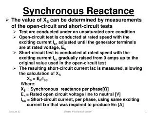
Armature Leakage Reactance(XL) Three major components -Slot leakage reactance, end winding leakage reactance and tooth tip leakage reactance. Synchronous reactance / phase Xs = XL + Xa , where Xa is the fictitious armature reaction reactance. Synchronous impedance/phase Zs = (Ra + jXs).
Armature Reaction Effect of the armature flux on the main field flux. Armature Reaction effect depends upon the PF of the Load UPF - cross magnetizing. Lag PF - demagnetizing. Lead PF - magnetizing
UPF (Pure Resistive Load) cross magnetizing Main Flux Φf Armature Flux Φa N S Main Flux Φf Iaph Φa Eph Induced EMF due to Main Flux Φf
Lagging PF (Purely Inductive Load) Demagnetizing Main Flux Φf Armature Flux Φa N S Armature Flux Φa Main Flux Φf Ia Load current Lag the Voltage by 90 Main Flux Decreases DC excitation Eph Induced EMF due to Main Flux Φf
Lead PF (Purely Capacitive Load) Magnetizing Main Flux Φf N S Armature Flux Φa Armature Flux Φa Main Flux Φf Ia Load current Lead the Voltage by 90 Main Flux Increases DC excitation Eph Induced EMF due to Main Flux Φf
VOLTAGE REGULATOR Voltage Regulator of an alternator is defined as the change in terminal voltage from NO load to full load divided by full-load voltage. % Voltage Regulator = E0 – V x 100 V There are different methods available to determine the voltage regulation of an alternator, 1.Direct loading method 2. Synchronous impedance method or E.M.F. method 3. Ampere-turns method or M.M.F. method 4. Zero power factor method or Potier triangle method 5. ASA modified from of M.M.F. method 6. Two reaction theory
The star connected armature is to be connected to a three phase load The field winding is excited by separate d.c. supply. To control the flux i.e. the current through field winding, a rheostat is inserted in series with the field winding. The prime mover drives the alternator at its synchronous speed. Eph αΦ ..... (From e.m.f. equation) For high capacity alternators, that much full load can not be simulated or directly connected to the alternator. Hence method is restricted only for small capacity alternators.
The method is also called E.M.F. method • The method requires following data to calculate the regulation. • The armature resistance per phase (Ra). • 2. Open circuit characteristics which is the graph of open circuit voltage against the field current. This is possible by conducting open circuit test on the alternator. • 3. Short circuit characteristics which is the graph of short circuit currentagainst field current. This is possible by conducting short circuit test on the alternator. Zs is calculated. Ra measured and Xs obtained. For a given armature current and power factor, Eph determined - regulation is calculated.